
Adjustable exhaust baffling device

a technology of baffling device and exhaust, which is applied in the direction of exhaust treatment, machines/engines, mechanical equipment, etc., can solve the problems of affecting the performance of these engines, unable to substantially control the noise of these devices, and devices that are difficult to fit in tight applications on cars, etc., to achieve the effect of maximizing engine performance and being easy to install

Inactive Publication Date: 2013-07-11
MITTLEIDER CORY LEE
View PDF2 Cites 3 Cited by
  • Summary
  • Abstract
  • Description
  • Claims
  • Application Information

AI Technical Summary

Benefits of technology

The invention is an improved exhaust baffle that can control the noise level of exhaust and maximize engine performance. It has a rotating baffle assembly that can be adjusted to different positions without tools. This device can be easily installed without modifying the exhaust system. The technical effect is to offer an efficient and flexible solution for controlling exhaust noise and performance levels.

Problems solved by technology

Internal combustion engines that have been tuned for high performance such as those found in race cars or motorcycles, often include an exhaust system that lacks any substantial noise control device.
This is necessarily the case, since noise control devices often impose restrictions to flow which would hinder the performance of these engines.
This type of device would be difficult to fit in tight applications on cars, and nearly impossible to practically install on a motorcycle.
Many times the required modification may not be desirable or even possible in the given application.

Method used


Image

  • Adjustable exhaust baffling device
  • Adjustable exhaust baffling device

Examples


Embodiment Construction

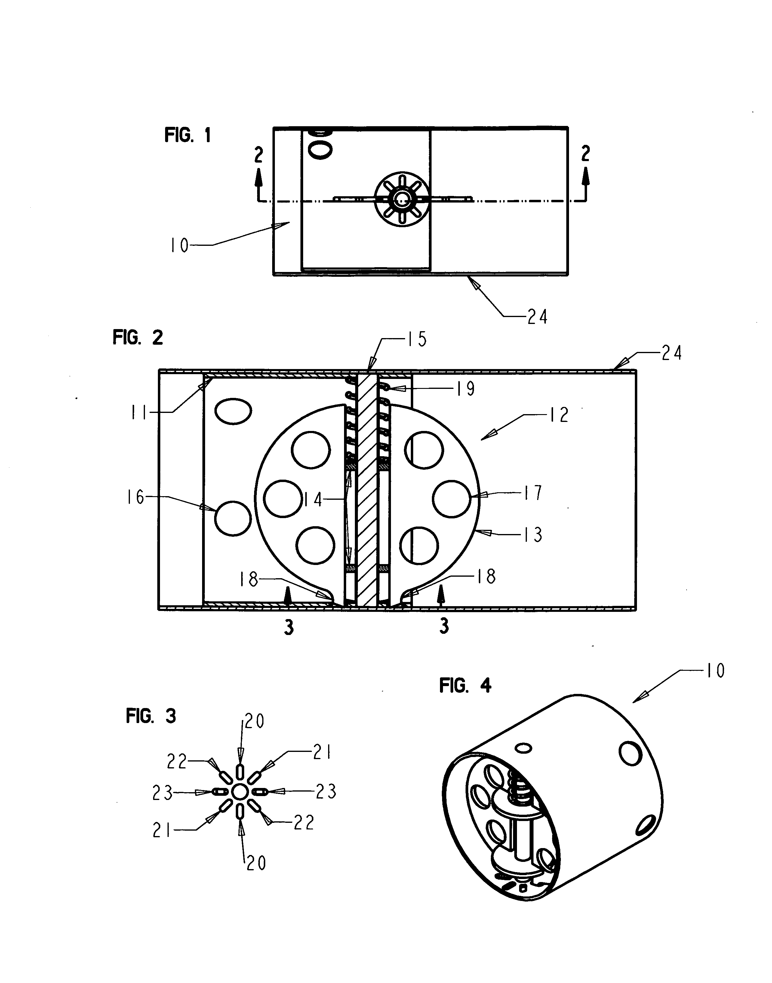
[0014]FIG. 1 shows a top view of the present invention generally designated 10 installed in a section of an existing exhaust system 24.

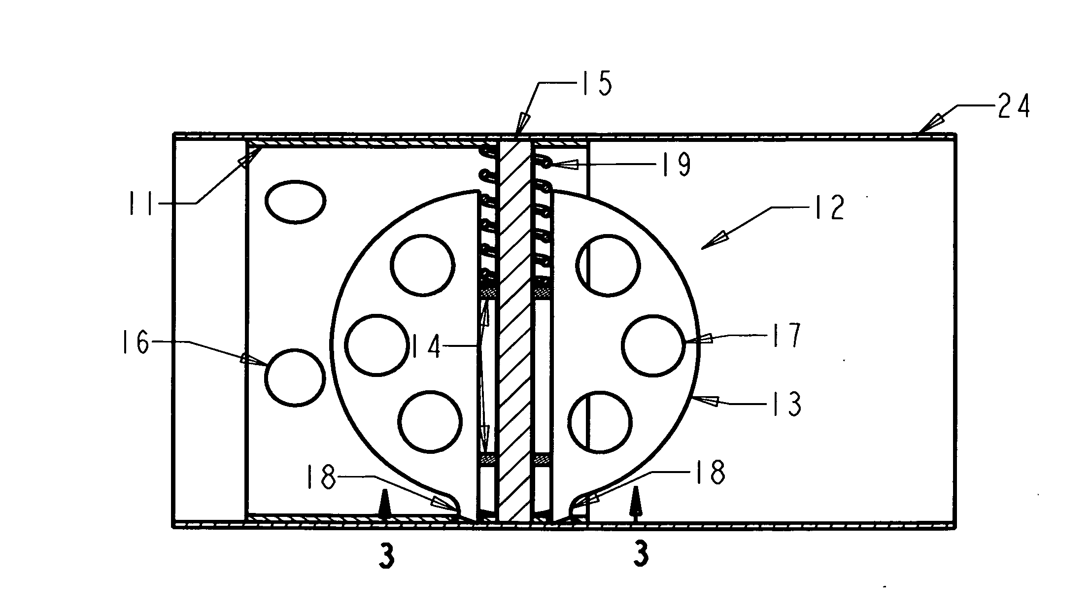
[0015]FIG. 2 illustrates two primary parts of the device. The first part is the tubular body 11 which creates the main body of the device. The second primary part is the baffle assembly generally designated 12 which provides the operational mode change as described by the present invention.

[0016]The baffle assembly 12 consists of two baffle plates 13 connected by two lifting tabs 14. The lifting tabs 14 provide for a means of lifting axially, and rotating about the pivot shaft 15. Each baffle plate 13 has a varying quantity, size, and pattern of passages 17 through which exhaust gas may pass when place transverse to exhaust flow. Each baffle plate 13 has a locking tab 18 that extends towards the tubular body 11 where there are corresponding slots that receive said tabs causing the baffle assembly 12 to rotationally lock in a position when acted upon ...


PUM


Abstract

An exhaust baffling assembly which allows for the operator of a motor vehicle to select between two or more modes varying between maximum noise control, and maximum performance. This device is easily installed in most motorcycle after-market exhaust systems by removing the supplied baffle, and mounting the presented device in the same mounting hole, making for a modification free installation. After this device is installed, the mode selections offered can be selected at the operators discretion by hand, and without tools.

Description

BACKGROUND OF THE INVENTION[0001]1. Field of the Invention[0002]This invention relates to the baffling device placed in the exhaust stream of an internal combustion engine. Specifically, it relates to a device that allows the operator to choose between varying noise control and performance levels.[0003]2. Description of the Prior Art[0004]Internal combustion engines that have been tuned for high performance such as those found in race cars or motorcycles, often include an exhaust system that lacks any substantial noise control device. This is necessarily the case, since noise control devices often impose restrictions to flow which would hinder the performance of these engines.[0005]Often the described vehicles are operated in residential areas where noise level mandates dictate a maximum lawful level of noise that may be produced by on-road vehicles.[0006]There are some devices currently available that offer a compromise between noise control, and performance. One of these devices i...

Claims


Application Information

Patent Timeline
Patent Type & Authority Applications(United States)
IPC IPC(8): F01N1/08
CPCF01N1/083F01N2240/36F01N1/168F01N1/165
Inventor MITTLEIDER, CORY LEE
Owner MITTLEIDER CORY LEE
Learn More