LED Lamp

Inactive Publication Date: 2013-07-11
CHIN WEN LUNG
View PDF2 Cites 3 Cited by
  • Summary
  • Abstract
  • Description
  • Claims
  • Application Information

AI Technical Summary

Benefits of technology

[0014]According to the primary advantage of the present invention, the base plate is integrally combined with the housing completely by injection molding so that the base plate and the housing are combined closely and solidly and will not detach from each other so as to enhance the structural strength of the LED lamp.
[0015]According to another advantage of the present invention, the base plate and the housing

Problems solved by technology

However, the base plate is not combined with the housing closely and tightly by screwing, thereby decreasing the structural strength of the LED

Method used


Image

  • LED Lamp
  • LED Lamp

Examples


Example

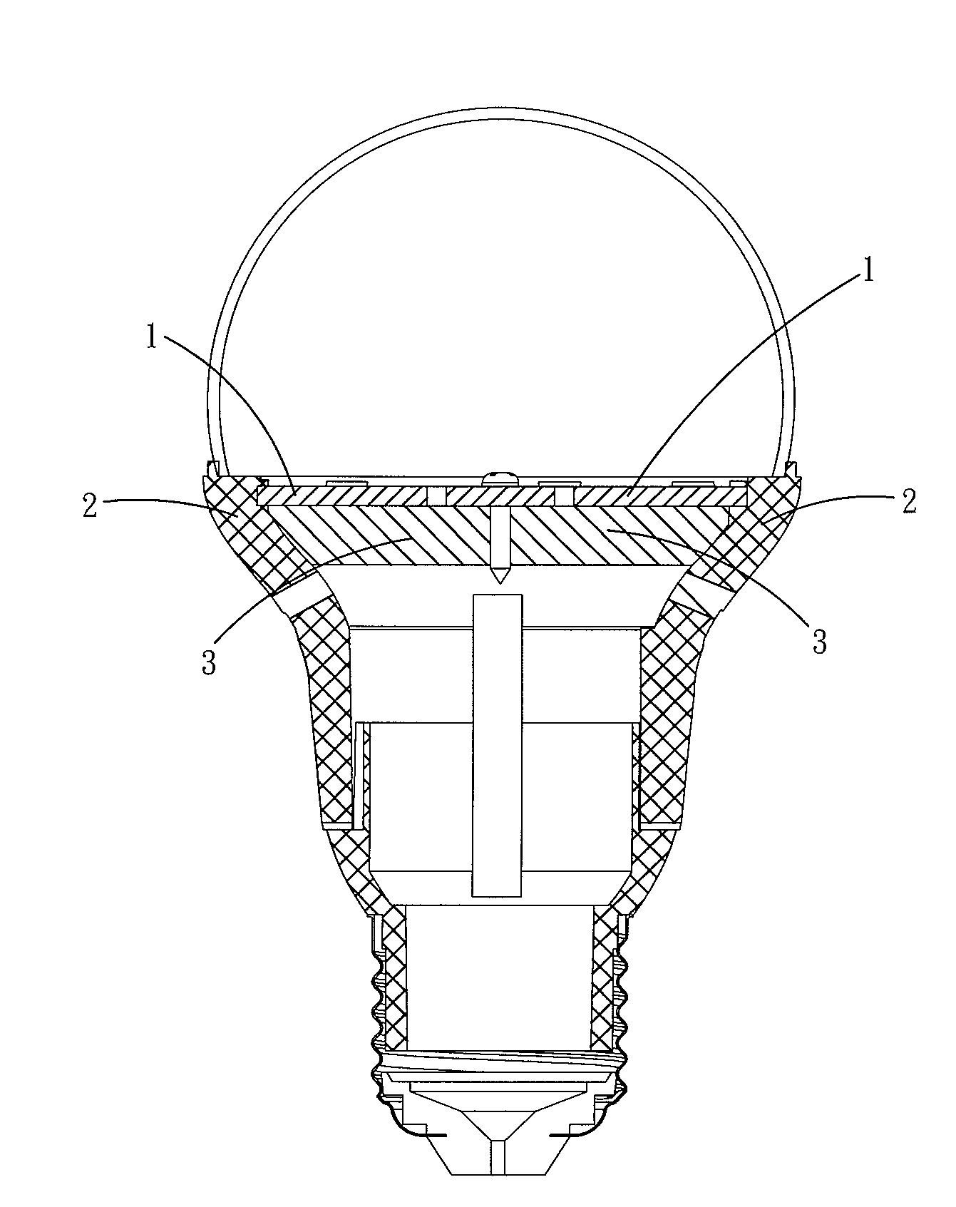
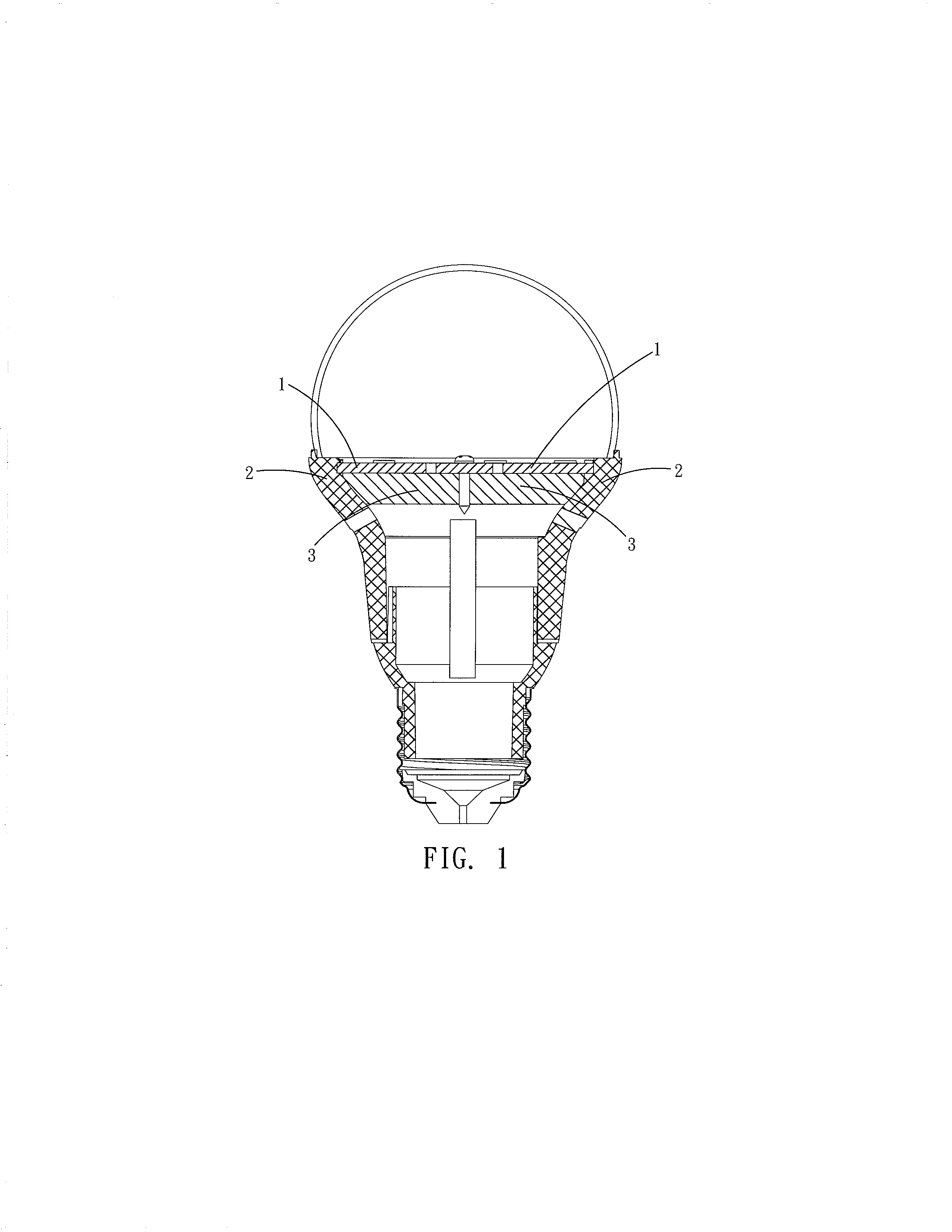
[0018]Referring to FIG. 1, an LED (light emitting diode) lamp in accordance with the preferred embodiment of the present invention comprises a housing 2, and a base plate 1 combined with the housing 2. The base plate 1 is integrally combined with the housing 2 by plastic injection molding. The base plate 1 is combined with an LED module (which is a modularized product) so that the base plate 1 and the LED module are packed to function as an LED light source. Alternatively, the base plate 1 is combined with at least one LED crystal so that the base plate 1 and the LED crystal are packed to function as an LED light source.

[0019]In fabrication, the base plate 1 is initially formed and worked. For example, the base plate 1 is flattened and drilled in the working process. Then, the base plate 1 is placed in a die cavity of an injection molding machine. Then, the housing 2 covers the base plate 1 during an injection molding process so that the base plate 1 is integrally combined with the ...


PUM


Abstract

An LED lamp includes a housing, and a base plate combined with the housing. The base plate is integrally combined with the housing by injection molding so that the base plate and the housing are combined closely and solidly and will not detach from each other.

Description

BACKGROUND OF THE INVENTION[0001]1. Field of the Invention[0002]The present invention relates to a lighting appliance and, more particularly, to an LED (light emitting diode) lamp.[0003]2. Description of the Related Art[0004]A conventional LED (light emitting diode) lamp comprises a housing, and a base plate combined with the housing. The base plate is combined with an LED module (which is a modularized product) so that the base plate and the LED module are packed to function as an LED light source. Alternatively, the base plate is combined with at least one LED crystal so that the base plate and the LED crystal are packed to function as an LED light source. The base plate has a plurality of screw holes, and the housing has a plurality of screw bores which are connected with the screw holes of the base plate by a plurality of screw members so that the base plate is combined with the housing by screwing. However, the base plate is not combined with the housing closely and tightly by ...

Claims


Application Information

Patent Timeline
IPC IPC(8): H01L33/64
CPCF21K9/135F21K9/232
Inventor CHIN, WEN-LUNG
Owner CHIN WEN LUNG
Why Eureka
Try Eureka