

Fan frame structure
- Summary
- Abstract
- Description
- Claims
- Application Information
AI Technical Summary
Benefits of technology
Problems solved by technology
Method used
Image

Examples
Embodiment Construction
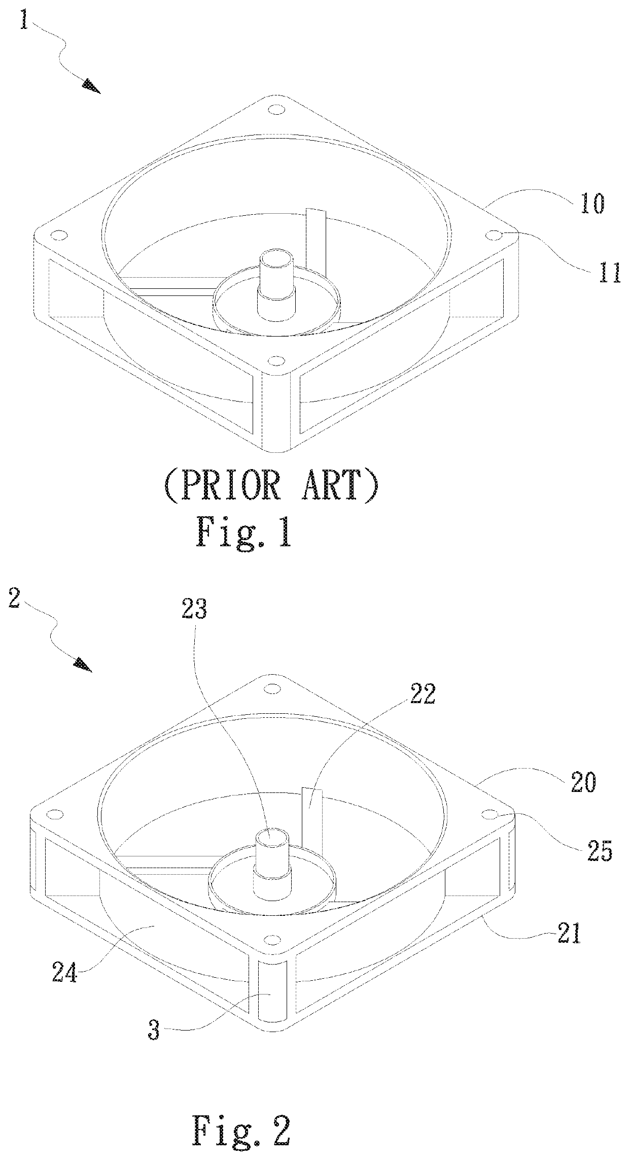
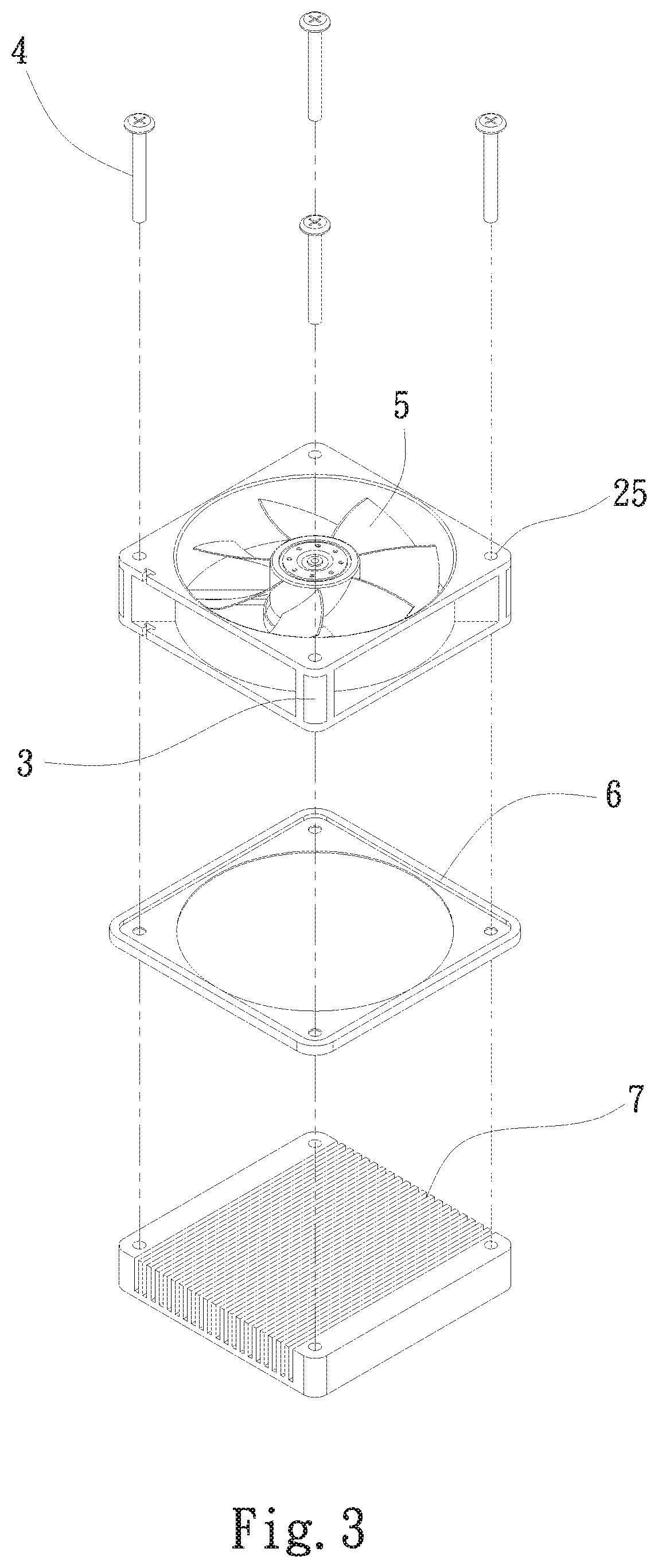
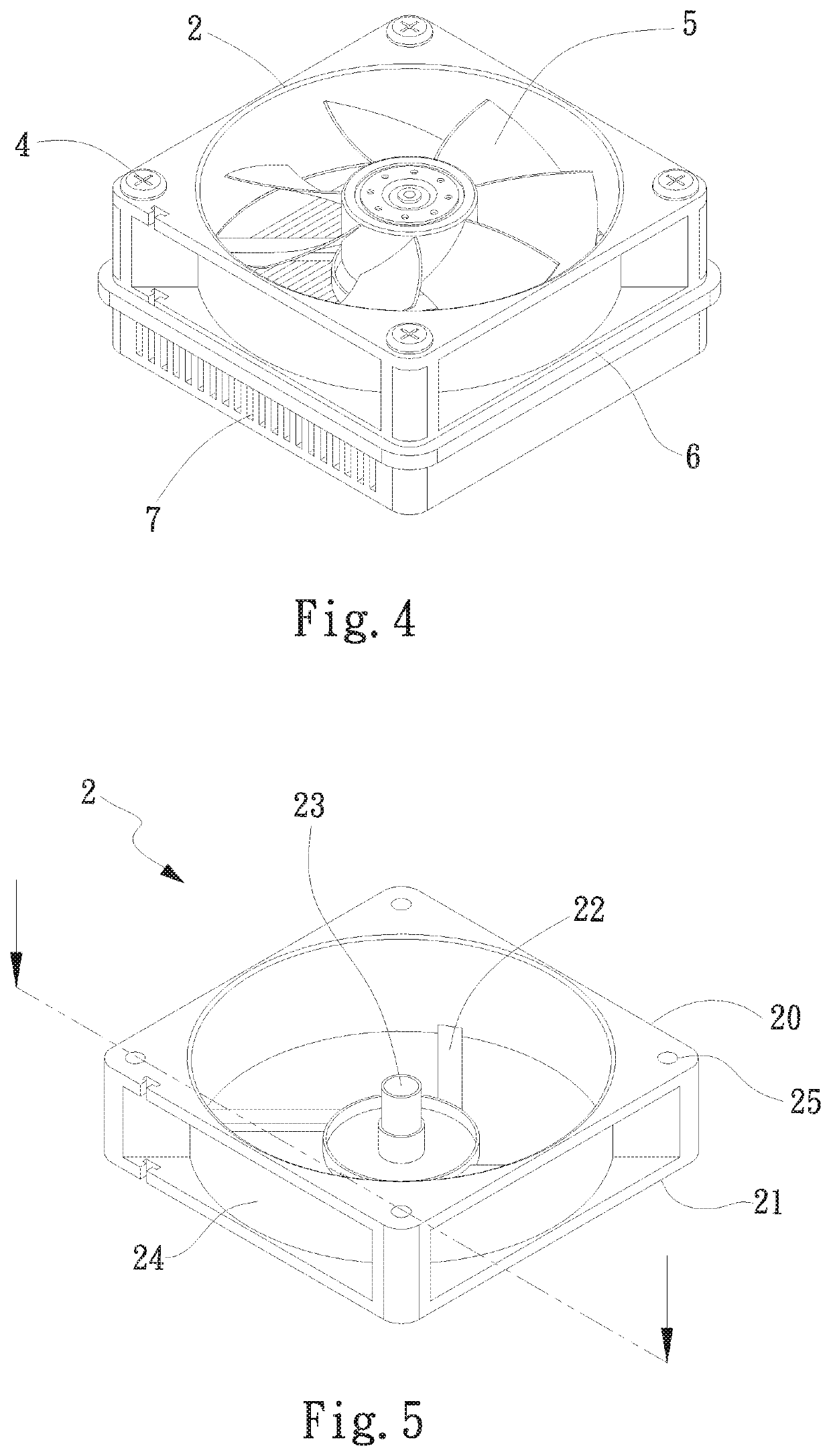
[0021]Please refer to FIGS. 2 to 4. FIG. 2 is a perspective view of a first embodiment of the frame body of the present invention. FIG. 3 is a perspective exploded view of the first embodiment of the fan frame structure of the present invention. FIG. 4 is a perspective assembled view of the first embodiment of the fan frame structure of the present invention. The fan frame structure of the present invention has a frame body 2. The frame body 2 has a base seat 22 and a circumferential wall 24. A bearing cup 23 upward extends from a center of the base seat 22. A fan impeller 5 is correspondingly pivotally disposed on the bearing cup 23. In this embodiment, the frame body 2 is, but not limited to, a rectangular frame body for illustration purposes. In practice, the frame body 2 can be alternatively a circular frame body 2. The frame body 2 further has a first side 20 and a second side. At least one locking hole 25 is formed on each of four corners of the first side 20. The locking hole...
PUM
 Abstract
Description
Claims
Application Information