Solar generator

a solar generator and generator technology, applied in the field of solar generators, can solve the problems of aging of solar generators, solar generator failure, faulty solar cells or cells, etc., and achieve the effect of better assessing failures

Active Publication Date: 2013-07-11
DEUTSCHES ZENTRUM FUER LUFT & RAUMFAHRT EV
View PDF2 Cites 7 Cited by
  • Summary
  • Abstract
  • Description
  • Claims
  • Application Information

AI Technical Summary

Benefits of technology

[0008]The object of the present disclosure is to specify a solar generator which makes it possible to better assess occurrences of failure of single or multiple solar cells.
[0019]To avoid having to analyze the electrical status of all first and second conductors with every collision, in a preferred refinement the second evaluation means is designed and configured so that in the event of a failure of one or more solar cells detected by the first evaluation means, the electrical status of just those first and second conductors is analyzed which according to the known associations, are associated with the failed solar cell or cells, that is, are arranged within the solar panel beneath the surface covered by the failed solar cell. This reduces considerably the energy required for monitoring and analysis.

Problems solved by technology

In spite of extensive ground tests, one or more solar cells of the solar generators fail during space missions.
Causes thereof include faulty solar cells or cells damaged during launch, aging of solar cells or the solar generators (during longer space missions), and in particular collision with objects in space.
Due to their large flat surface area, solar panels in particular are at risk of potentially colliding with space objects, that is, naturally occurring micrometeorites and “space debris” generated by human space activity.
While the danger caused by naturally occurring micrometeorites remains temporally virtually unchanged, the risk of collision with so-called space debris at least in earth orbit has continually increased over the past decades.
The damage caused to solar generators due to collision with such space objects given their high relative velocity (several kilometers per second) can be severe even in the case of small sized particles, to the point of resulting in the aborting of a mission.
Frequently, colliding space objects puncture the solar panels thereby destroying single or multiple solar cells.
Most space objects are too small for purposes of ground-based locating methods, as the frequency of the space objects is reciprocal to their size.

Method used


Image

  • Solar generator
  • Solar generator
  • Solar generator

Examples


first embodiment

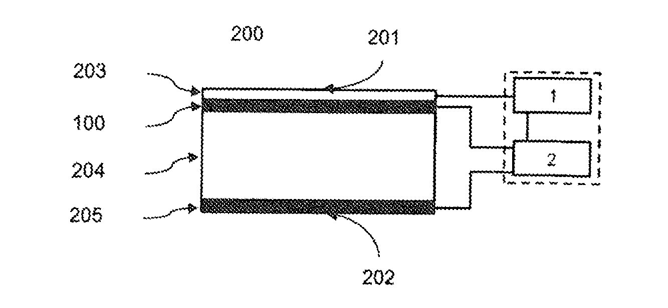
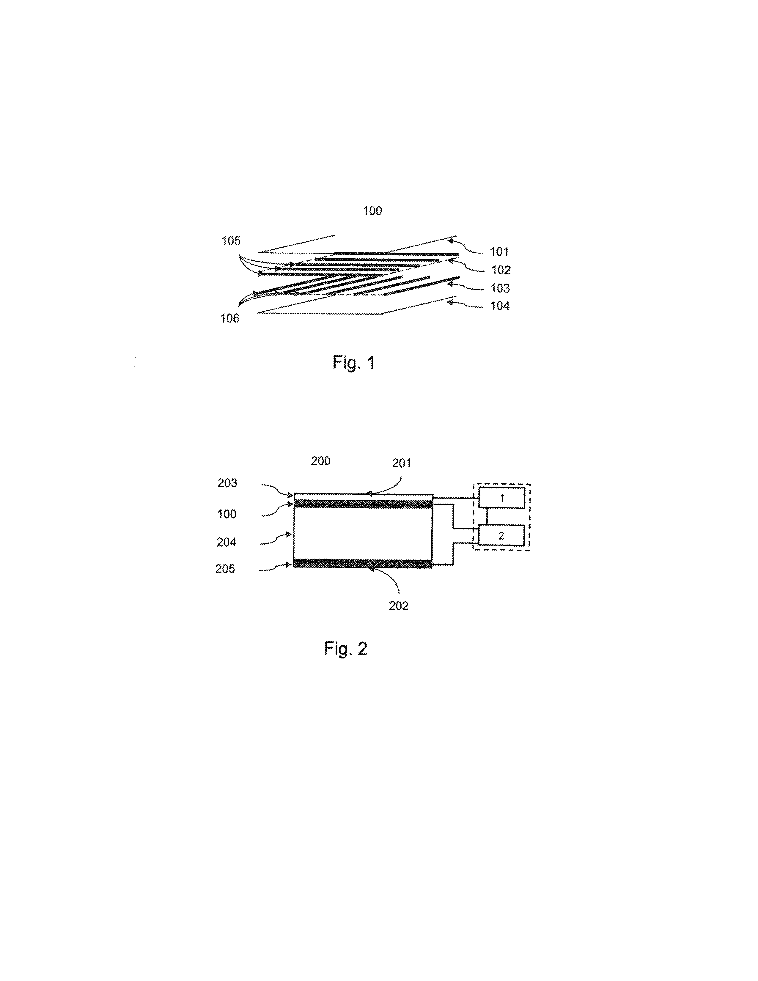
[0045]FIG. 2 is a schematic view of a solar generator according to the present disclosure with a cross-sectional view of a solar panel 200. The flat expansive solar panel 200 with an upper side 201 and an underside or backside 202 has the following layered structure (from top to bottom):[0046]layer of solar cells 203;[0047]first detector layer 100;[0048]structural layer 204; and[0049]second detector layer 205.

[0050]A first evaluation means 1 is connected to the solar cells 207 (as best shown in FIG. 5) and is configured and designed to individually detect a failure of one or several of the solar cells 207. The first evaluation means 1 does not determine the cause of the failure of the solar cell(s) 207. A second evaluation means 2 is connected to the first evaluation means 1 and to the first electrical conductors 105 and the second electrical conductors 106 of the first detector layer 100, as well as to third electrical conductors 208 and fourth electrical conductors 209 of the seco...

second embodiment

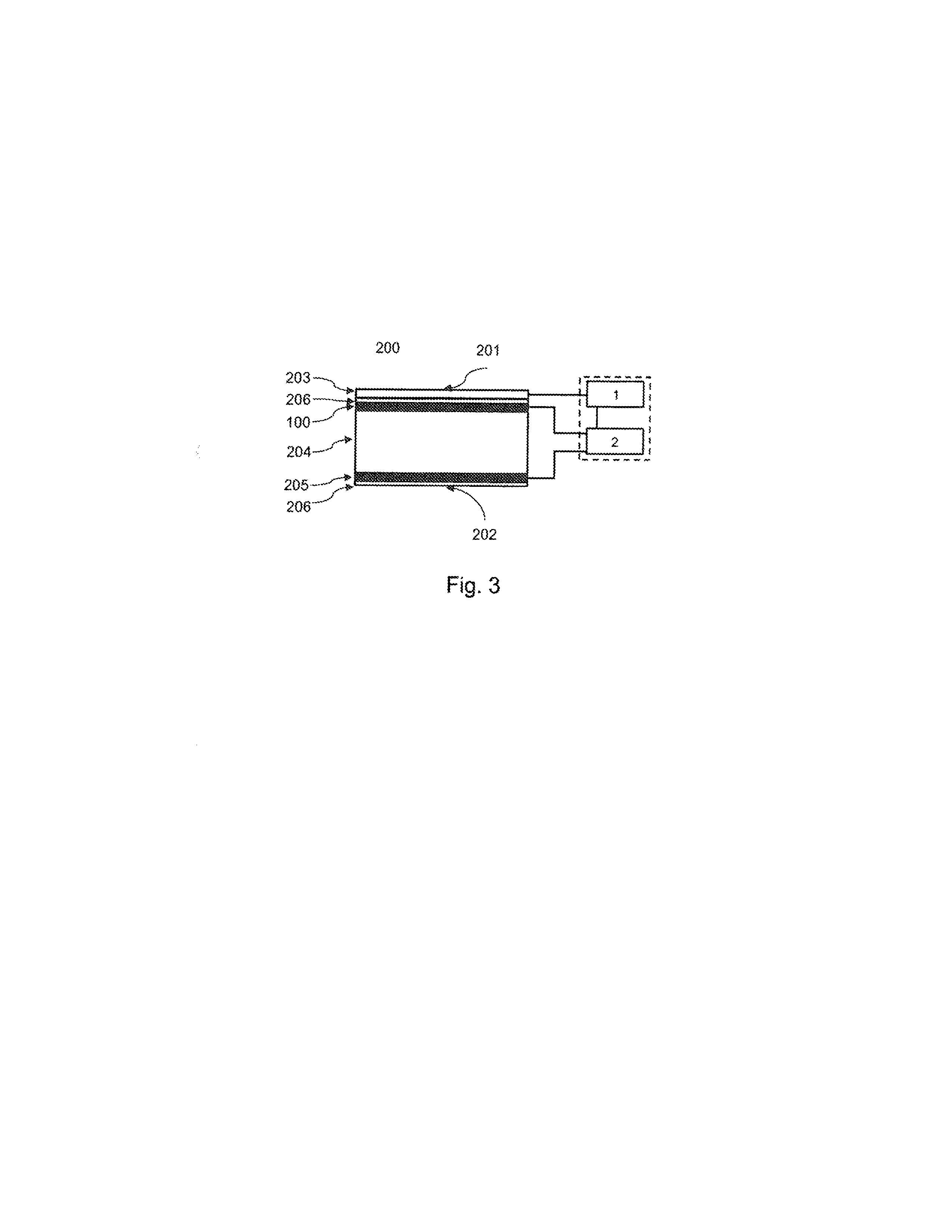
[0053]FIG. 3 is a schematic representation of a solar generator. The representation is based on FIG. 2 and differs from FIG. 2 in that a separating layer 206 is arranged on the underside of the solar panels 200 and between the layer of solar cells 203 and the first detector layer 100, respectively. This separating layer 206 preferably comprises an insulating material and further includes a conductive fabric for shielding from electrical fields.

third embodiment

[0054]FIG. 4 is a schematic representation of a solar generator. The representation is based on FIG. 3 and differs from FIG. 3 in that a separating layer 206 is arranged between the first detector layer 100 and the structural layer 204, and between the structural layer 204 and the second detector layer 205, respectively. This separating layer 206 preferably comprises an insulating material and further includes a conductive fabric for shielding from electrical fields.

[0055]FIG. 5 is a partially transparent representation of an upper side 201 of a solar panel 200 in schematic plan view. Visible on the upper side 201 are the solar cells 207 in grid-like arrangement and arranged beneath these solar cells 207 in the solar panel 200 are the first electrical conductor 105 and second electrical conductor 106 of the first detector layer 100. Each of the electrical conductors 105, 106 is connected to the second evaluation unit 2 (not shown). Clearly visible is the association of the first ele...


PUM


Abstract

A solar generator for spacecraft or satellites, including a solar panel, a detector layer, a first evaluation means and a second evaluation means. The solar panel includes a plurality of solar cells. The detector layer includes first conductors substantially in parallel in a first plane and second conductors substantially in parallel in a second plane. The second plane is substantially in parallel to the first plane such that the first conductors are at an angle to the second conductors. The first evaluation means is for detecting a failure of one or more of the plurality of solar cells. The second evaluation means is for testing electrical status of the first conductors and the second conductors to determine whether the failure detected by the first evaluation means was caused by a space object damaging or severing one or more of the first conductors and the second conductors.

Description

CROSS REFERENCE TO RELATED APPLICATION[0001]This application claims priority to German Patent Application No. 102012000260.2, filed on Jan. 10, 2012, which is incorporated herein by reference in its entirety.BACKGROUND[0002]1. Field of Technology[0003]The present disclosure relates to a solar generator for spacecraft or satellites. More particularly, the present disclosure is directed to a solar generator that makes it possible to better assess occurrences of failure of single or multiple solar cells.[0004]2. Brief Discussion of Related Art[0005]Spacecraft and satellites are commonly known to use solar generators for generating energy in space. Typically, solar generators comprise large solar panels and solar cells that are deployable in space and which convert light into electrical energy, in addition to control electronics and suitable cabling. In spite of extensive ground tests, one or more solar cells of the solar generators fail during space missions. Causes thereof include fau...

Claims


Application Information

Patent Timeline
Patent Type & Authority Applications(United States)
IPC IPC(8): G01R31/26
CPCB64G1/56G01R31/2605B64G1/44
Inventor BAUER, WALDEMARROMBERG, OLIVER
Owner DEUTSCHES ZENTRUM FUER LUFT & RAUMFAHRT EV
Why Eureka
Try Eureka