Method and device for providing temporally consistent disparity estimations

a technology of temporally consistent disparity estimation and estimation method, which is applied in the field of three-dimensional video imaging, can solve the problems of difficult to know exactly what is the destination pixel of a given pixel, difficult to achieve exact and secure computation of disparities, and much more difficult problems, so as to reduce at least in part the discomfort

Active Publication Date: 2013-07-11
INTERDIGITAL MADISON PATENT HLDG
View PDF2 Cites 1 Cited by
  • Summary
  • Abstract
  • Description
  • Claims
  • Application Information

AI Technical Summary

Benefits of technology

[0013]The invention aims at reducing at least in part this discomfort due to undesirable artifacts.
[0034]By “zero value” is meant a value below a threshold which is at most equal to the acquisition noise of the images. The bilateral filtering will lower the noise in the image so that the still zones will have luminances very close to zero.

Problems solved by technology

The computation of disparities is not an exact and secure computation.
The reason is that it may be difficult to know exactly what is the destination pixel for a given pixel.
However, for more complex portions of images, such as images with rather uniformly colored zones and no precise contour, it is much more difficult and the estimator will not be able to precisely determine what point corresponds to what point.
It is much more annoying in a video sequence because the computer will do the estimation for each pair of images but may arrive to different estimations in different pairs of images even though the depth of the object in the real scene has not changed from a pair to the next successive pairs.
This variation in the estimations from image to image will result, at the time of reproduction on a display, in artifacts such as flickering or jittering, false colors, etc.
They are uncomfortable for the viewer.

Method used


Image

  • Method and device for providing temporally consistent disparity estimations
  • Method and device for providing temporally consistent disparity estimations
  • Method and device for providing temporally consistent disparity estimations

Examples


Embodiment Construction

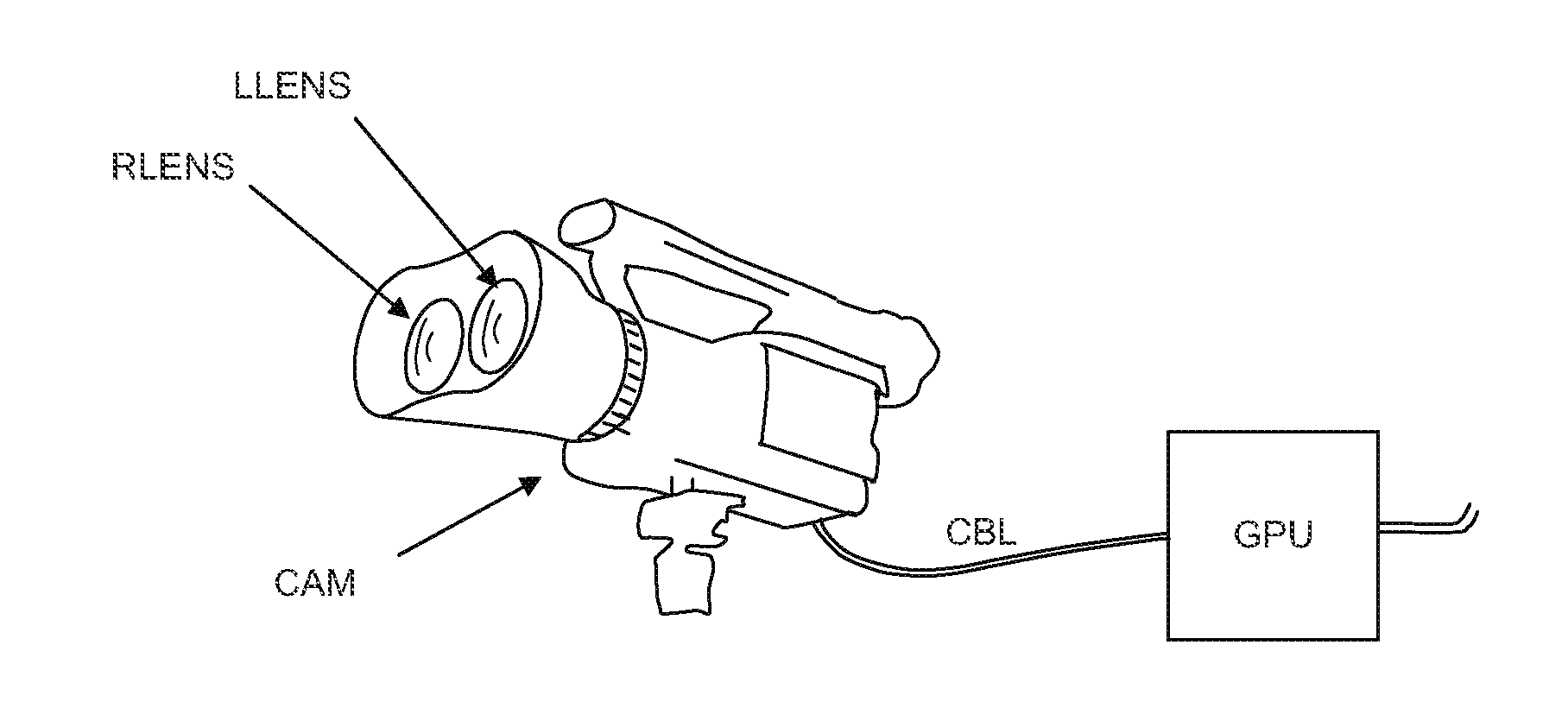
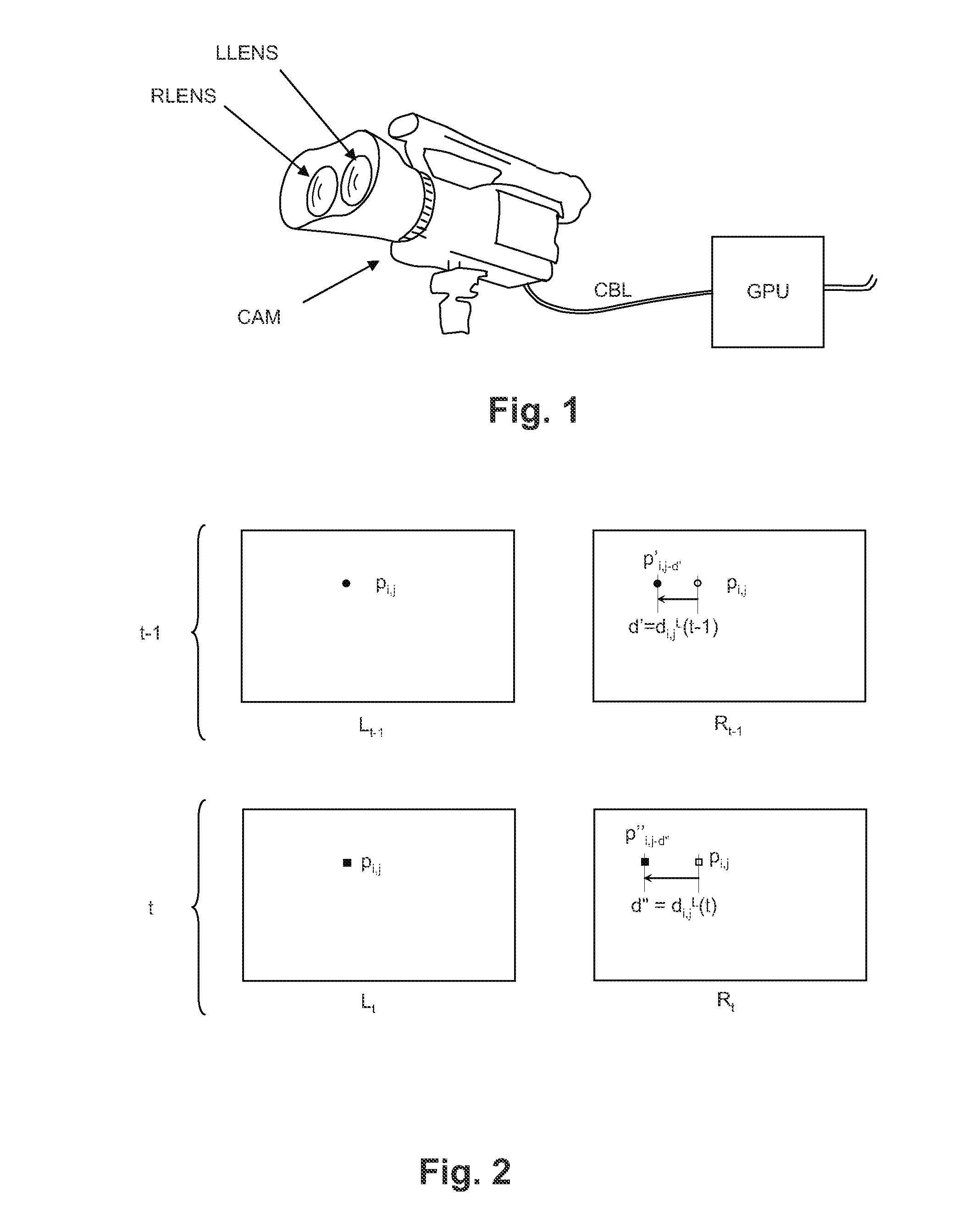
[0050]FIG. 1 shows a camera CAM for three dimensional video recording. The camera has two lenses LLENS (left lens) and RLENS (right lens). A respective electronic matrix image sensor is coupled to each lens so as to produce two images for each frame. The images may be recorded on a recording support (not shown, inserted in the camera body) in view of being processed later in processing means, or they may be sent through cable means CBL or wireless communicating means (not shown) for processing. The processing means includes means for estimating disparities. They may be incorporated in the camera and then the camera records or sends not only the images but also a map of disparities. The processing means may alternatively be external to the camera. The processing means may be a graphics processing unit in a computer or in a video display. For the sake of simplicity, the processing means have been represented on FIG. 1 as a box GPU, external to the bi-lens camera and linked to the came...


PUM


Abstract

The invention relates to three dimensional video imaging, in which at least a left view and a right view of a moving scene are produced and a map of disparities is produced for all pixels of the successive images of a video sequence.

Description

FIELD OF THE INVENTION[0001]The invention relates to three dimensional video imaging, in which at least a left view and a right view of a moving scene are produced and a map of disparities is produced for all pixels of the successive images of a video sequence. The purpose of the invention is to provide an improved manner of associating disparities to successive images.BACKGROUND OF THE INVENTION[0002]Disparity is a geometrical quantity associated with each point of a two-dimensional image to reflect a depth of the point of the scene in a three-dimensional representation.[0003]If one considers an object-point observed by a left camera and a right camera which produce respectively a left image and a right image, the disparity is the difference between the position of this object-point in the left image and in the right image. It depends directly from the “depth” of the object-point, i.e. its distance to the cameras.[0004]Disparity is expressed in an integer and fractional number of p...

Claims


Application Information

Patent Timeline
Patent Type & Authority Applications(United States)
IPC IPC(8): H04N13/00H04N13/122
CPCH04N13/0018H04N13/0239H04N13/0022H04N13/122H04N13/128H04N13/239
Inventor BOISSON, GUILLAUMEKERBIRIOU, PAULDRAZIC, VALTER
Owner INTERDIGITAL MADISON PATENT HLDG
Why Eureka
Try Eureka