
Image forming apparatus

a technology of forming apparatus and forming tube, which is applied in the direction of electrographic process apparatus, instruments, optics, etc., can solve the problems of metal salt of fatty acid (, zinc stearate) losing its lubricity, poor image,

Active Publication Date: 2013-07-11
RICOH KK
View PDF8 Cites 35 Cited by
  • Summary
  • Abstract
  • Description
  • Claims
  • Application Information

AI Technical Summary

Benefits of technology

The patent describes an image forming apparatus that uses a protective agent to improve the transfer of toner from an intermediate transfer body to a recording member. The apparatus includes an image carrier that carries an electrostatic latent image, a developing unit that develops the image using toner, an intermediate transfer body that carries the toner image, a secondary transfer member that comes in contact with the intermediate transfer body to form a transfer nip, a power supply that outputs a voltage to transfer the toner image onto the recording member, and a first protective agent supply unit that introduces a protective agent containing zinc stearate and boron nitride onto the image carrier. The invention, which alternates the voltage in a transfer direction and an opposite direction, improves the transfer of toner images and also reduces the occurrence of image transfer failures.

Problems solved by technology

This can be considered due to deterioration of the image carrier, the charging member, and the cleaning member.
This deterioration results from occurrence of an electrical stress in a charging step by a charging unit for electrically charging the photosensitive element.
However, in Japanese Patent 51-22380, it is obvious that metal salt of fatty acid (representatively, zinc stearate) loses its lubricity in the early stage, by the effect of the discharge performed in the vicinity of the image carrier during the charging step.
As a result, the lubricity between the cleaning blade and the image carrier is lowered, and the toner passes therethrough, resulting in a poor image.
Thus, as disclosed in Japanese Patent Application Laid-open No. 2006-350240, even if the protective agent with a compound of metal salt of fatty acid and boron nitride is applied to the intermediate transfer belt, no particular effect is attained in the normal image formation with application of only a DC electric field, in spite of the high cost.

Method used


Image

  • Image forming apparatus
  • Image forming apparatus
  • Image forming apparatus

Examples


first embodiment

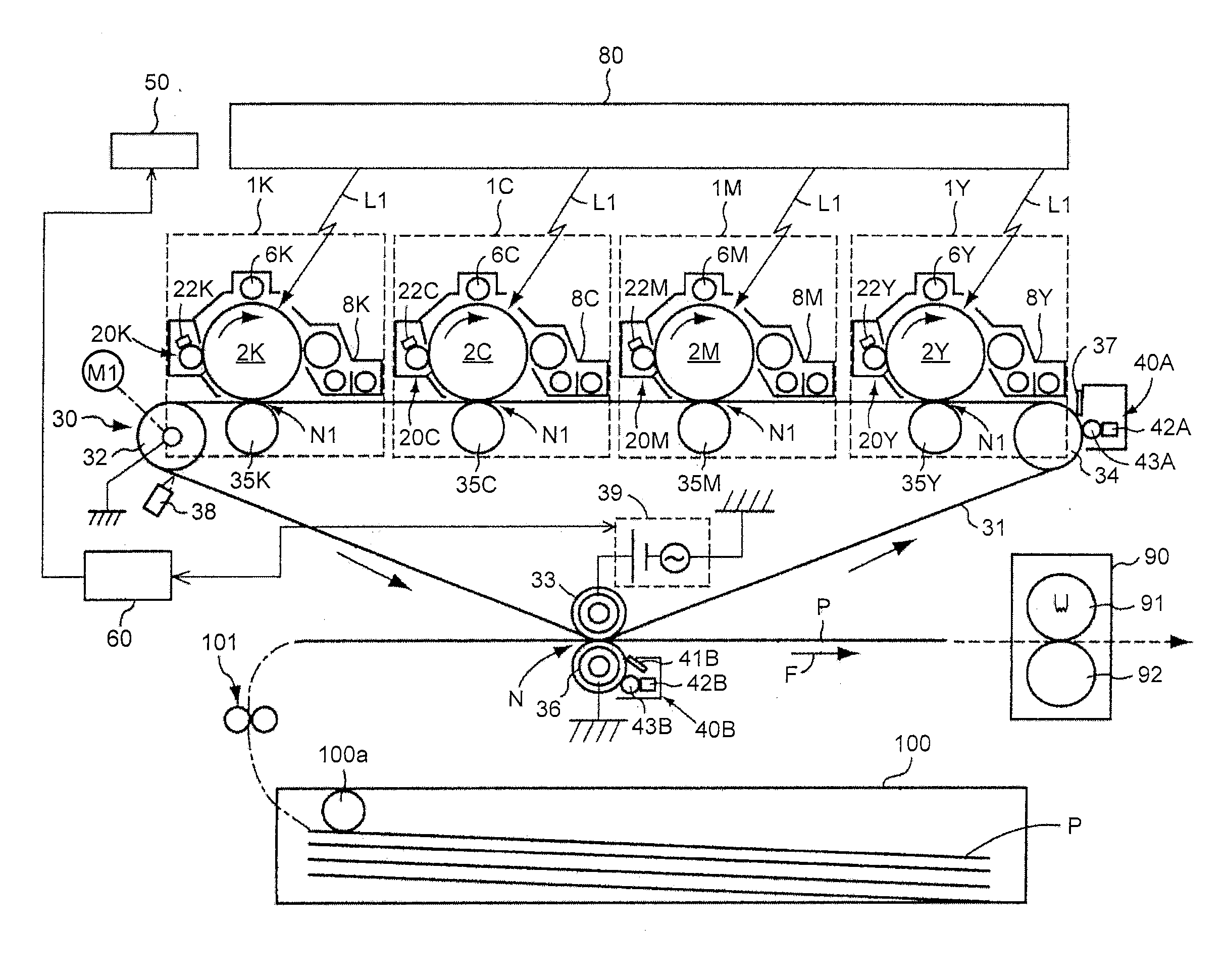
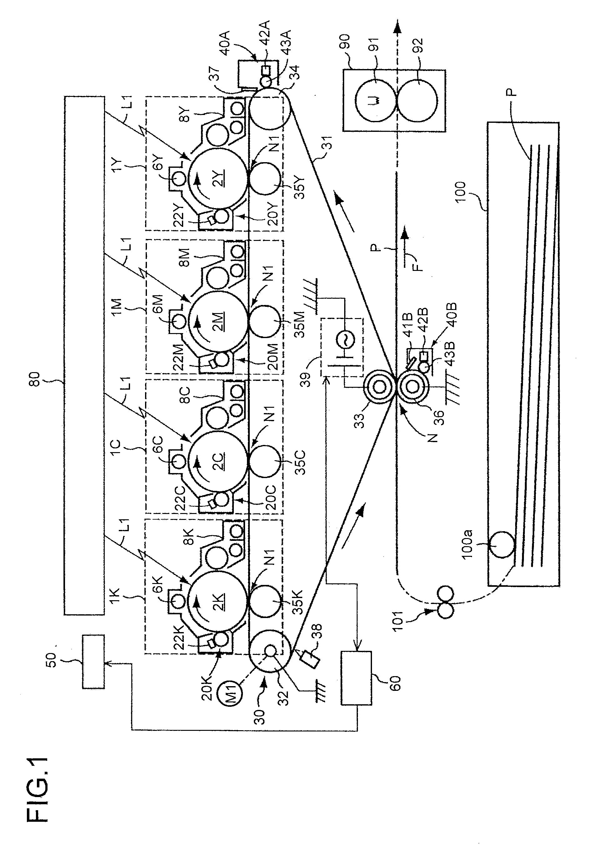
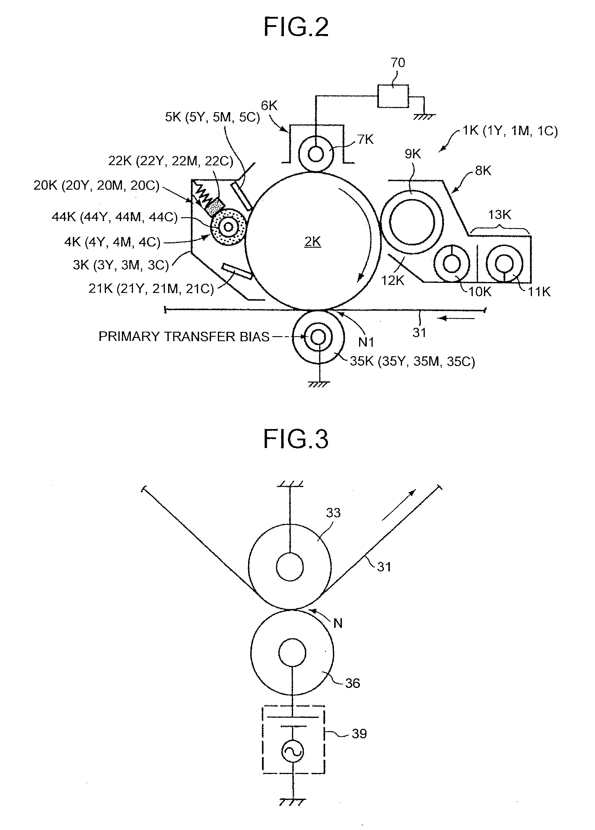
[0034]An image forming apparatus according to the embodiment of FIG. 1 is an electrophotography color printer (hereinafter simply referred to as a “printer”). FIG. 1 is a schematic block diagram illustrating the printer according to this embodiment. In this illustration, the printer includes four image forming units 1Y, 1M, 1C, and 1K for forming a yellow (Y) toner image, a magenta (M) toner image, a cyan (C) toner image, and a black (K) toner image. The printer includes a transfer unit 30 as a transfer device, an optical writing unit 80, a fixing device 90, a paper cassette 100, and a control unit60 as a controlling device.

[0035]The four image forming units 1Y, 1M, 1C, and K respectively use Y, M, C, and K toners that are different from each other, as image forming materials. The rest of the elements are the same between the units, and are replaced with a new one at the end of their lives. The image forming unit 1K for forming a K toner image will now be described by way of example...

example 1

[0111]As a protective agent, the protective agent B was applied to each photosensitive element, and no application was made to the intermediate transfer belt 31 and the nip-forming roller 36. A secondary transfer bias having a sine wave of FIG. 11 was applied.

example 2

[0112]As a protective agent, the protective agent B was applied to each photosensitive element, and also was applied to the intermediate transfer belt 31 and the nip-forming roller 36. A secondary transfer bias having a sine wave was applied.


PUM


Abstract

An image forming apparatus includes an image carrier that carries an electrostatic latent image; a developing unit that develops the electrostatic latent image using a toner; an intermediate transfer body onto which toner image is transferred; a secondary transfer member that comes in contact with a surface of the intermediate transfer body; a power supply that outputs a voltage for transferring the toner image on the intermediate transfer body onto a recording member; and a protective agent supply unit that applies a protective agent including zinc stearate and boron nitride onto a surface of the image carrier. The voltage is alternatively switched in a transfer direction and an opposite direction. The voltage in the transfer direction enables transfer of the toner image from the intermediate transfer body to the recording member, and the voltage in the opposite direction has polarity opposite to polarity of the voltage in the transfer direction.

Description

CROSS-REFERENCE TO RELATED APPLICATIONS[0001]The present application claims priority to and incorporates by reference the entire contents of Japanese Patent Application No. 2012-003399 filed in Japan on Jan. 11, 2012 and Japanese Patent Application No. 2012-247794 filed in Japan on Nov. 9, 2012.BACKGROUND OF THE INVENTION[0002]1. Field of the Invention[0003]The present invention relates to an image forming apparatus, which supplies a protective agent to an image carrier and uses a voltage including an AC bias for transferring a toner image formed on the image carrier to a recording member.[0004]2. Description of the Related Art[0005]Typical examples of an image forming apparatus are an electrographic copier, a FAX, a printer, and an MFP in combination with these multi-functions. Japanese Patent Application Laid-open No. 2006-267486 discloses a known technique for transferring the toner image on the surface of the image carrier toward the recording member which has been put in the tr...

Claims


Application Information

Patent Timeline
IPC IPC(8): G03G15/16G03G21/00
CPCG03G15/0189G03G15/161G03G15/1695G03G21/0094G03G15/168
Inventor TANAKA, SHINYAISHII, HIROKAZUOGIYAMA, HIROMISHIMIZU, YASUNOBUNAKAMURA, KEIGO
Owner RICOH KK
Learn More