Carbon dioxide gas fixation method and carbon dioxide gas fixation apparatus

a carbon dioxide and gas fixation technology, applied in the field of carbon dioxide gas fixation methods and equipment, can solve the problems of methods imposing environmental burdens, and achieve the effects of promoting phytoplankton propagation, without impact, and without impa

Active Publication Date: 2013-07-18
IHI CORP
View PDF7 Cites 5 Cited by
  • Summary
  • Abstract
  • Description
  • Claims
  • Application Information

AI Technical Summary

Benefits of technology

[0016]With the carbon dioxide gas fixation method of the present invention, seawater is electrolyzed, anodic electrolyzed water and cathodic electrolyzed water produced by the electrolysis of the seawater are separated, alkaline material is inputted into the anodic electrolyzed water to adjust pH, carbon dioxide gas is blown into the cathodic electrolyzed water to fix the carbon dioxide gas as carbonate, and the anodic electrolyzed water after pH adjustment and the cathodic electrolyzed water after carbonate fixation are intermixed, and discharged with a pH identical to that of seawater. Consequently, it is possible to fix carbon dioxide gas without impact on the environment.
[0017]In the carbon dioxide gas fixation method of the present invention, it is possible to concomitantly perform treatment of industrial waste products when using waste concrete as the alkaline material.
[0018]In the carbon dioxide gas fixation method of the present invention, when using iron, which is a soluble metal, in the anode-side electrode, ferric ions are dissolved in the anodic electrolyzed water in the seawater electrolysis process, and ferric ions that are a nutrient of phytoplankton are supplied into the seawater. As a result, propagation of phytoplankton is promoted, achieving fixation of carbon dioxide gas by phytoplankton.
[0019]According to the carbon dioxide gas fixation apparatus of the present invention, there is provided: an electrolysis tank which has an anode and a cathode; a barrier membrane which partitions an interior of the electrolysis tank into an anode-side region containing the anode, and a cathode-side region containing the cathode; a first treatment tank which stores anodic electrolyzed water produced in the anode-side region; a second treatment tank which stores cathodic electrolyzed water produced in the cathode-side region; a power-supply unit which supplies power to the anode and the cathode; an alkaline material input device which inputs alkaline material into the first treatment tank; and a carbon dioxide gas blower which blows carbon dioxide gas into the second treatment tank, in which wastewater from the first treatment tank and wastewater from the second treatment tank are intermixed, and discharged. Consequently, it is possible to fix carbon dioxide gas without impact on the environment.
[0020]In the carbon dioxide gas fixation apparatus of the present invention, when the power-supply unit has at least one photovoltaic cell, fuel cell, wind power generator, wave power generator, ocean thermal energy generator, or solar thermal power generator, power is supplied by utilizing natural energy, or by using energy that does not produce carbon dioxide gas. Consequently, it is possible to fix carbon dioxide gas without impact on the environment.
[0021]In the carbon dioxide gas fixation apparatus of the present invention, when the power-supply unit contains a fuel cell which uses hydrogen gas generated on the cathode side, and oxygen gas generated on the anode side, a portion of the power expended in seawater electrolysis is again used in seawater electrolysis. Consequently, energy conservation is achieved.

Problems solved by technology

However, the foregoing methods not only impose environmental burdens, but also involve possibility of re-release of the carbon dioxide gas stored in the ocean or underground.

Method used


Image

  • Carbon dioxide gas fixation method and carbon dioxide gas fixation apparatus
  • Carbon dioxide gas fixation method and carbon dioxide gas fixation apparatus
  • Carbon dioxide gas fixation method and carbon dioxide gas fixation apparatus

Examples


Embodiment Construction

[0029]Embodiments of the present invention are described below with reference to drawings.

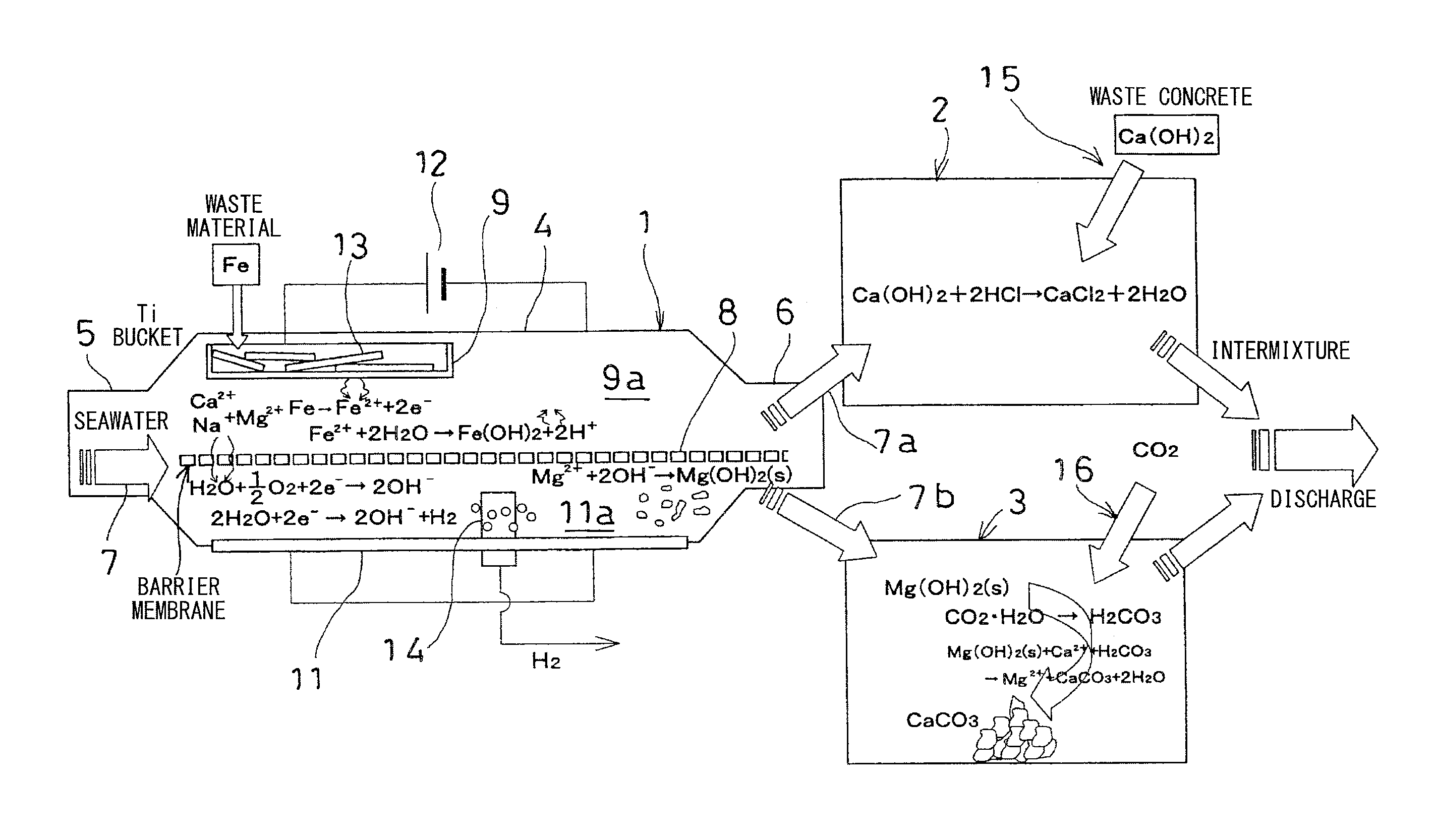
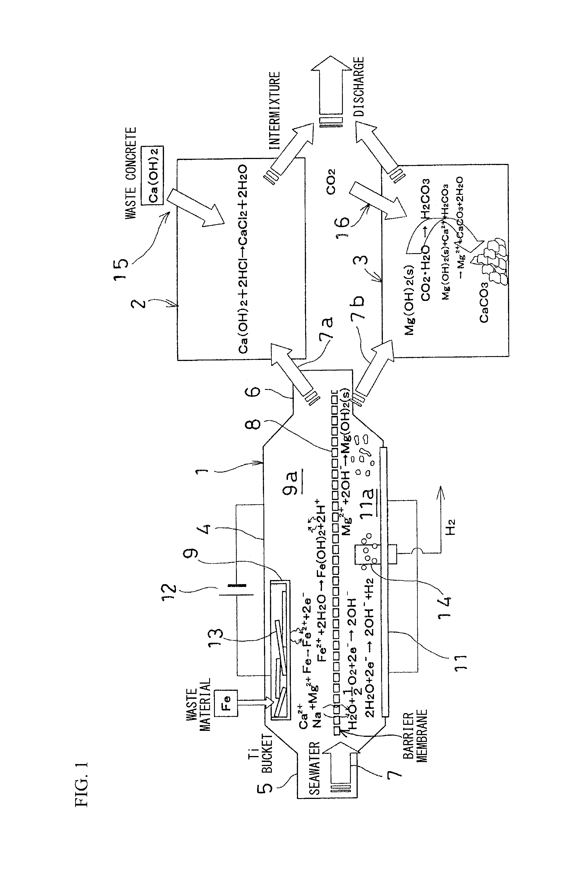
[0030]First, the principles of an embodiment of the present invention are described in FIG. 1.

[0031]In FIG. 1, 1 indicates an electrolysis tank, 2 indicates a first treatment tank, and 3 indicates a second treatment tank.

[0032]The electrolysis tank 1 has an electrolytic treatment container 4 made of corrosion-resistant material such as stainless steel, and the electrolytic treatment container 4 has an inlet 5 at the upstream end, and an outlet 6 at the downstream end. Seawater 7, which flows in from the inlet 5, runs uniformly through the interior of the electrolytic treatment container 4, and is discharged from the outlet 6.

[0033]Various methods may be adopted as a method of forming the flow of the seawater 7. For example, the electrolytic treatment container 4 may be submerged in water to utilize ocean current, and have the seawater 7 flow through the interior of the electrolytic treatment co...


PUM

PropertyMeasurementUnit
pHaaaaaaaaaa
poweraaaaaaaaaa

Abstract

In the carbon dioxide gas fixation method and carbon dioxide gas fixation apparatus, seawater (7) is electrolyzed, anodic electrolyzed water (7a) and cathodic electrolyzed water (7b) produced by electrolysis of the seawater are separated, alkaline material is inputted into the anodic electrolyzed water to adjust pH, carbon dioxide gas is blown into the cathodic electrolyzed water to fix the carbon dioxide gas as carbonate, and the anodic electrolyzed water after pH adjustment and the cathodic electrolyzed water after carbonate fixation are intermixed, and discharged in a state where a pH of the intermixed water is identical to a pH of the seawater. As a result, it is possible to offer a carbon dioxide gas fixation method and a carbon dioxide gas fixation apparatus which fix carbon dioxide gas with little impact on the environment, and without risk of re-release.

Description

TECHNICAL FIELD[0001]The present invention relates to carbon dioxide gas fixation method and apparatus which fix carbon dioxide gas by producing an alkaline solution from electrolysis of seawater, absorbing carbon dioxide gas into the seawater, and converting it to calcium carbonate.[0002]Priority is claimed on Japanese Patent Application No. 2010-193816, filed Aug. 31, 2010, the content of which is incorporated herein by reference.BACKGROUND ART[0003]Carbon dioxide gas has been cited as one factor in global warming, and emissions of carbon dioxide gas have increased in conjunction with economic growth. Accordingly, there is a serious need for reducing the atmospheric concentration of carbon dioxide gas on a global scale.[0004]Conventionally, as carbon dioxide gas fixation methods, there has been proposal of a method in which carbon dioxide gas is absorbed by an alkaline solution such as amine, and is separated and recovered by heating; or a method in which carbon dioxide gas that h...

Claims


Application Information

Patent Timeline
Patent Type & Authority Applications(United States)
IPC IPC(8): B01D53/14C01B32/50C01B32/60C25B9/19
CPCB01D53/62B01D53/965B01D2251/304B01D2252/1035B01D2257/504C01B31/24C02F2201/46165C02F1/46104C02F2103/08Y02C10/04C25B9/08B01D53/14C02F1/66C01F11/18Y02W10/37Y02P20/133C01B32/60Y02C20/40Y02P20/151C25B9/19
Inventor IWAMOTO, TATSUSHIAKAMINE, KENICHIOKUYAMA, JUNICHI
Owner IHI CORP
Why Eureka
Try Eureka