Glow plug terminal and glow plug

Active Publication Date: 2013-07-18
NGK SPARK PLUG CO LTD
View PDF5 Cites 7 Cited by
  • Summary
  • Abstract
  • Description
  • Claims
  • Application Information

AI Technical Summary

Benefits of technology

[0011]A pin terminal for a glow plug of the present invention comprises:
[0012]a small-diameter portion which has a shaft shape extending in an axial direction and is to be connected to a conductive member for supplying electric power from an outside;
[0013]a flange that is formed integrally with a front end of the small-diameter portion and is formed so as to have an outer diameter larger than an outer diameter of the small-diameter portion;
[0014]a cylindrical large-diameter portion that is formed integrally with a front end of the flange so as to be shorter than the small-diameter portion in the axial direction, is formed so as to have an outer diameter larger than the outer diameter of the small-diameter portion and sma

Problems solved by technology

For this reason, in the pin terminal, the reduction in the amount of material has been insufficient and the reduction in weight has been insufficient.
Further, since the glow p

Method used


Image

  • Glow plug terminal and glow plug
  • Glow plug terminal and glow plug
  • Glow plug terminal and glow plug

Examples


Example

[0062]An embodiment of the invention will be described below with reference to the drawings.

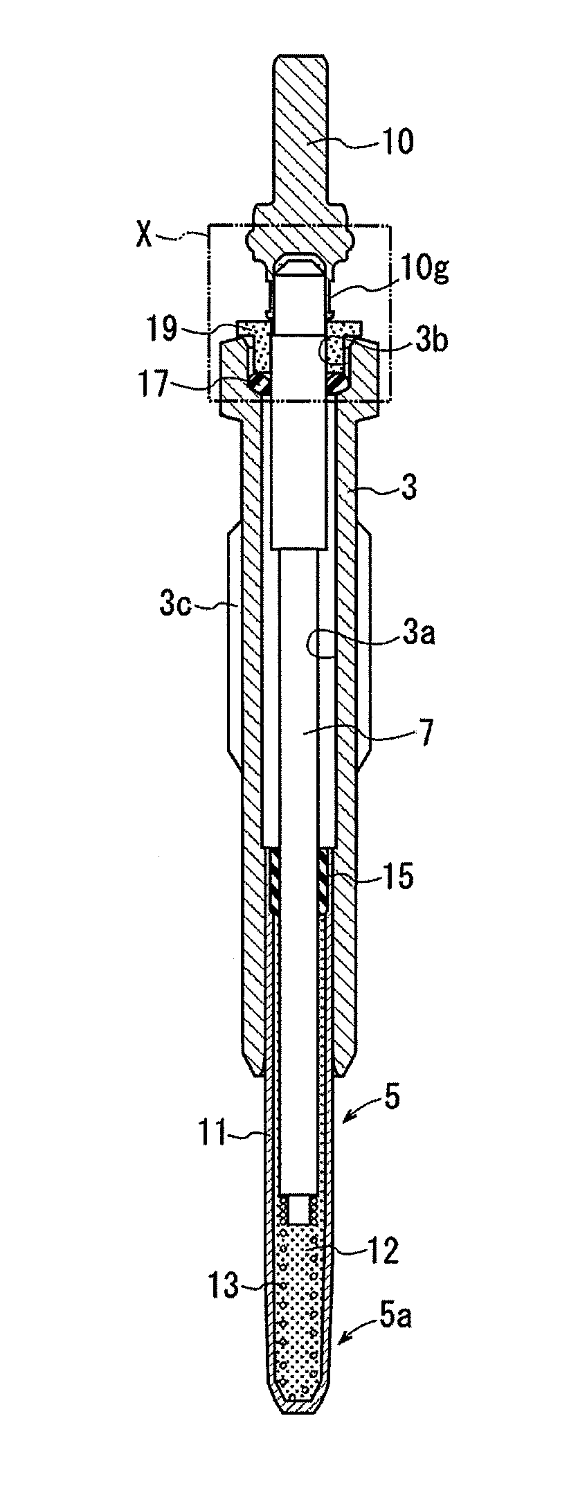
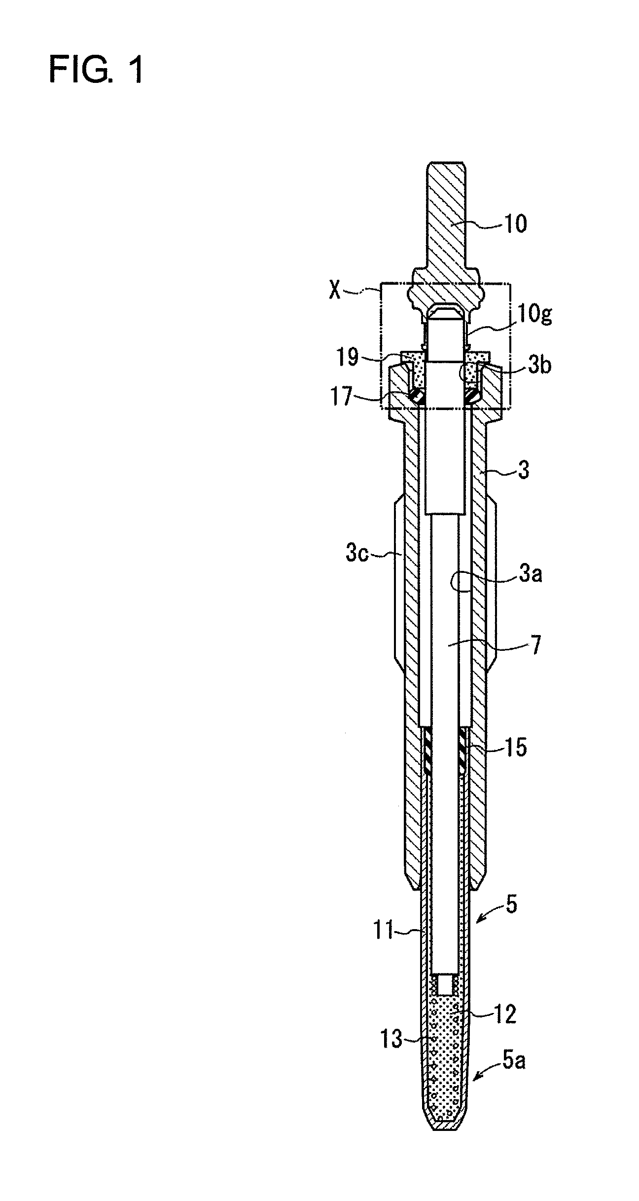
[0063]As shown in FIG. 1, a glow plug of an embodiment includes a main body bracket 3 as a cylindrical housing, a heater 5 that is fixed in the main body bracket 3 and includes a heat generating portion 5a protruding from a front end of the main body bracket 3, a rod-like center shaft 7 which is disposed in the main body bracket 3 and includes a rear end portion protruding from a rear end of the main body bracket 3, and a pin terminal 10 that is fitted to the rear end portion of the center shaft 7 and is used to apply an electricity to the heat generating portion 5a from the outside through the center shaft 7.

[0064]The heater 5 includes a heat generating tube 11 having a front end being closed. The heat generating tube 11 has the shape of a cylinder extending in the axial direction, and is fixed in the main body bracket 3 so that current can flow while a front end portion of the heat generati...


PUM

PropertyMeasurementUnit
Lengthaaaaaaaaaa
Diameteraaaaaaaaaa

Abstract

A glow plug having a main body bracket, a heater, a center shaft, an insulator, an O-ring that is provided between the front end surface of the insulator and the main body bracket, and a pin terminal that is fitted to the rear end portion of the center shaft and used for supplying electricity from the outside. The pin terminal includes a small-diameter portion, a flange, and a large-diameter portion where an engagement portion and a fitting recess are formed. The large-diameter portion includes a crimp formation region, which is formed so as to have the even outer diameter and be capable of being crimped, in a range from the front end thereof to the front end of the engagement portion. A part of the crimping target portion forms a crimping portion that fixes the rear end portion of the center shaft by crimping.

Description

FIELD OF THE INVENTION[0001]The present invention relates to a pin terminal for a glow plug and a glow plug.BACKGROUND OF THE INVENTION[0002]JP-A-2002-260827 discloses a conventionally known glow plug. As shown in FIG. 11, the glow plug includes a cylindrical housing 90, a heater 91 that is fixed in the housing 90 and includes a heat generating portion 91a protruding from the front end of the housing 90, a rod-like center shaft 92 which is disposed in the housing 90 and includes the rear end portion protruding from the rear end of the housing 90, and a pin terminal 93 that is fitted to the rear end portion of the center shaft 92 and is used to supply electricity to the heat generating portion 91a from the outside through the center shaft 92.[0003]The heater 91 is a ceramic heater which is fitted into an outer cylinder 94 fitted to the front end of the housing 90 and made of a conductive metal and includes the heat generating portion 91a protruding from the front end of the outer cyl...

Claims


Application Information

Patent Timeline
IPC IPC(8): H01R13/04F23Q7/22
CPCF23Q7/001F23Q7/22Y10T29/49204H01R43/00H01R13/04F23Q2007/004F23Q7/00
Inventor OKUMURA, YUKI
Owner NGK SPARK PLUG CO LTD
Why Eureka
Try Eureka