Active antivibration device and manufacturing method for the same

Inactive Publication Date: 2011-07-28
TOKAI RUBBER IND LTD +1
View PDF8 Cites 32 Cited by
  • Summary
  • Abstract
  • Description
  • Claims
  • Application Information

AI Technical Summary

Benefits of technology

In the present invention, using the foregoing assembly process, the second flat spring member can be fixed to the ceiling surface of the housing in advance before the housing and the base body are assembled. T

Problems solved by technology

As a result, a magnetic loss in the magnetic flux path increases, and an improvement of a magnetic propulsion force, that is, the improvement of a vibration applying force to be giv

Method used


Image

  • Active antivibration device and manufacturing method for the same
  • Active antivibration device and manufacturing method for the same
  • Active antivibration device and manufacturing method for the same

Examples


Example

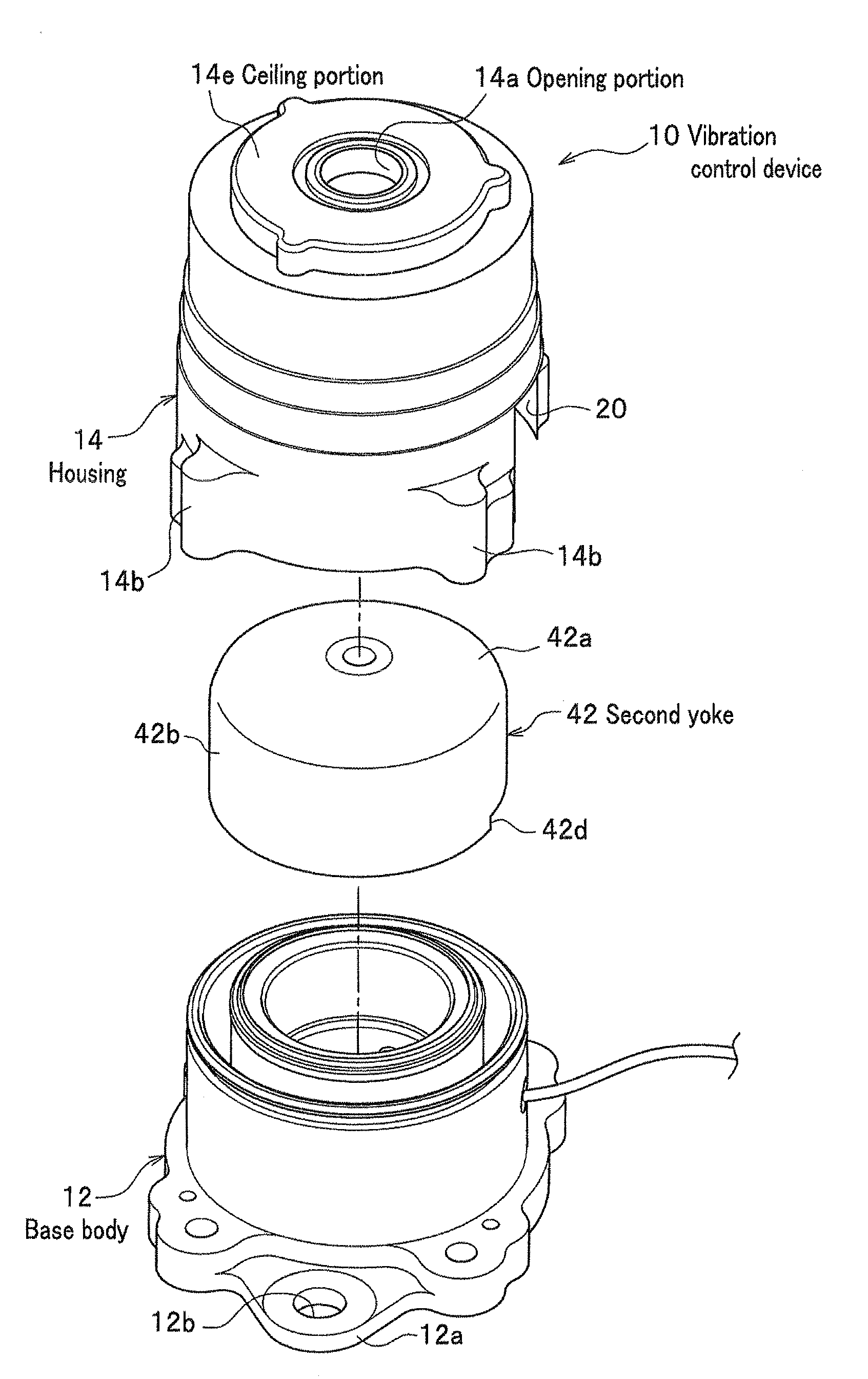
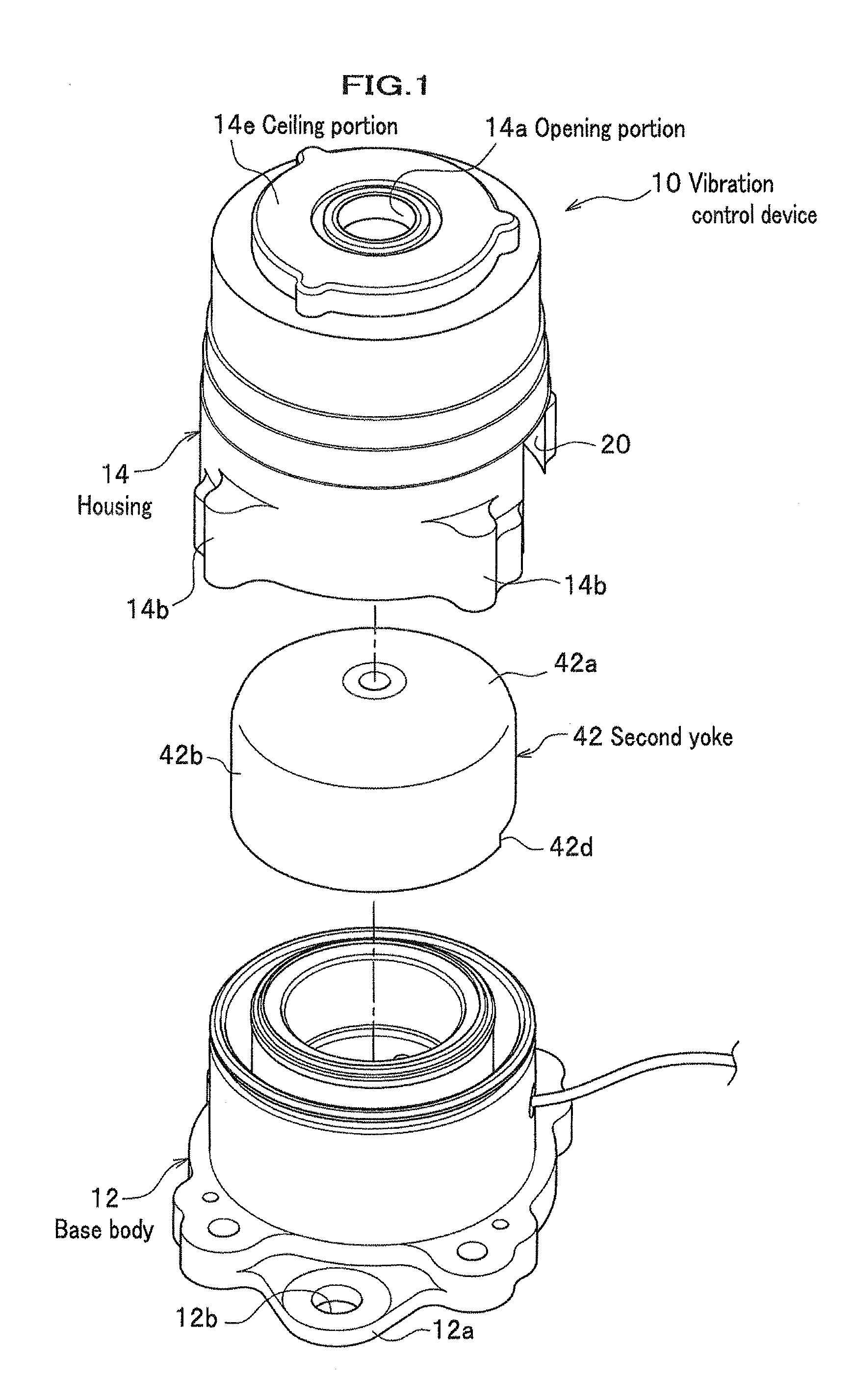
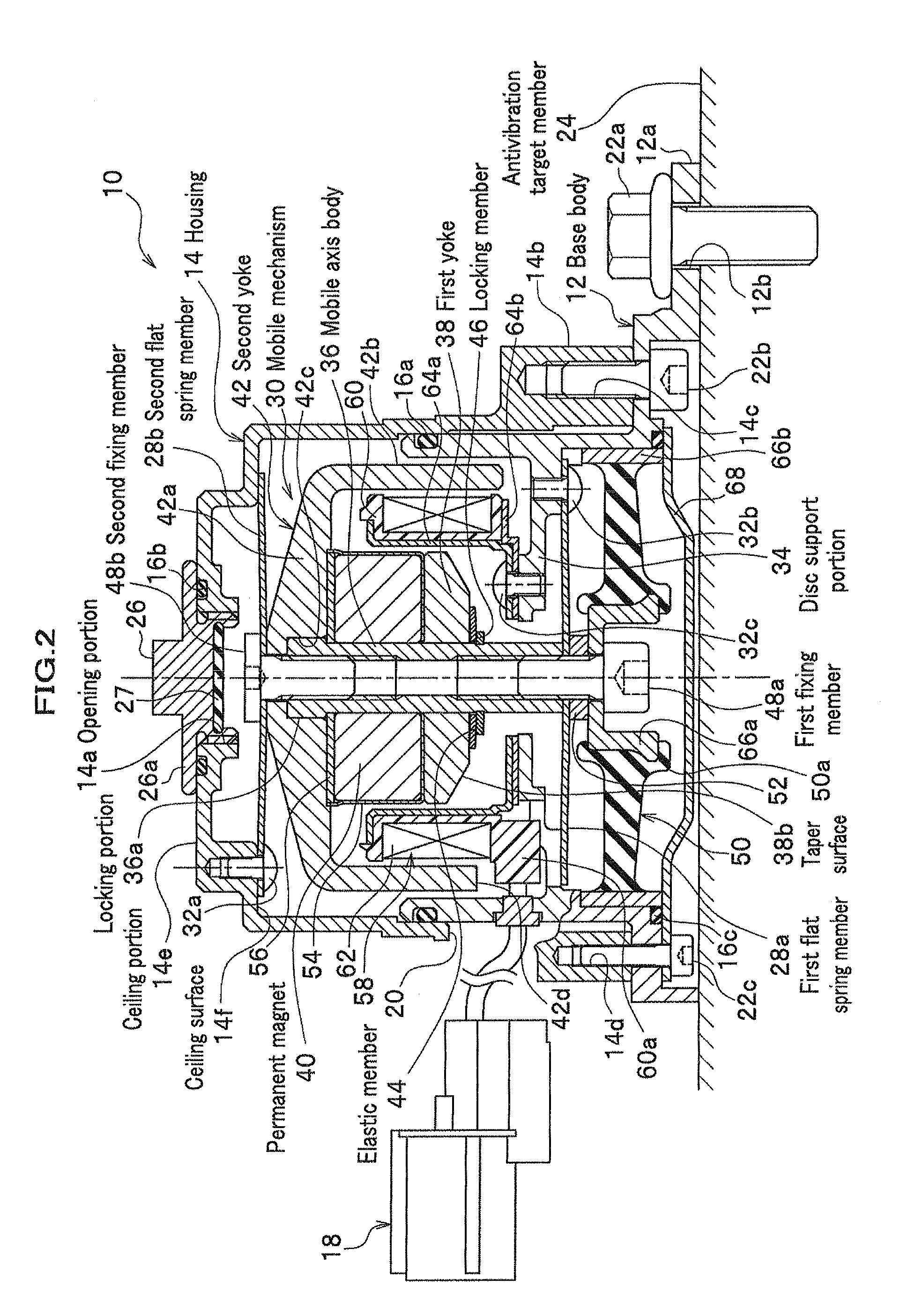
As shown in FIG. 1 and FIG. 2, a vibration control device 10 includes a base body 12 on the bottom side and a housing 14 on the upper side, and a main body is formed by a combination of the base body 12 and the housing 14 in a unified manner. Namely, one end portion on the upper side of the base body 12, which is opened at both end portions along the axial direction, is engaged with an opening side end portion of a bottom portion of the housing 14, which is formed in a bottomed cylindrical shape, to be jointed in a unified manner. It is noted that a sealing member 16a is disposed in a jointing portion between the base body 12 and the housing 14 using an annular groove, and inside of the housing 14 and the base body 12 is optimally sealed. In addition, in the housing 14, a cutout portion 20 which functions as a back clearance of a coupler 18, which will be described later, is formed.

The base body 12 on the bottom side consists of substantially a cylindrical body having substantially ...


PUM

PropertyMeasurementUnit
Diameteraaaaaaaaaa
Shapeaaaaaaaaaa
Distanceaaaaaaaaaa

Abstract

An active antivibration device which includes a main body, a mobile element which is elastically supported inside the main body and movable in an axial direction of the main body, and a coil which is disposed inside the main body and fixed to the main body. The mobile element includes a mobile axis body supported in the axial direction of the main body, and a first yoke, a permanent magnet and a second yoke which are held by the mobile axis body and disposed successively along an axial direction of the mobile axis body. The permanent magnet is magnetized in the axial direction of the mobile axis body and disposed between the first yoke and the second yoke.

Description

CROSS REFERENCE TO RELATED APPLICATIONSThis application claims the foreign priority benefit under Title 35, United States Code, §119(a)-(d) of Japanese Patent Applications No. 2010-016236 and No. 2010-016237, both filed on Jan. 28, 2010, the contents of which are hereby incorporated by reference.BACKGROUND OF THE INVENTION1. Field of the InventionThe present invention relates to an active antivibration device on an antivibration target member and capable of demonstrating an active antivibration effect by vibrating a mobile element by applying a current to a coil, and to a manufacturing method of the active antivibration device.2. Description of Related ArtFor example, in order to reduce vibrations of an antivibration target member which is required to reduce vibrations such as a body of a vehicle, generally, a vibration attenuating mechanism utilizing an attenuation effect of, for example, a shock absorber and a rubber elastic body, or a vibration isolating mechanism utilizing a spr...

Claims


Application Information

Patent Timeline
IPC IPC(8): F16F15/03H02K41/035F16F13/00B23P11/00
CPCF16F7/1011Y10T29/49826H02K41/0356H02K33/16
Inventor URAYAMA, ATSUSHIKON, HIROZUMIKOYAMA, HIRONORIMURAOKA, MUTSUMIMURAMATSU, ATSUSHI
Owner TOKAI RUBBER IND LTD
Why Eureka
Try Eureka