

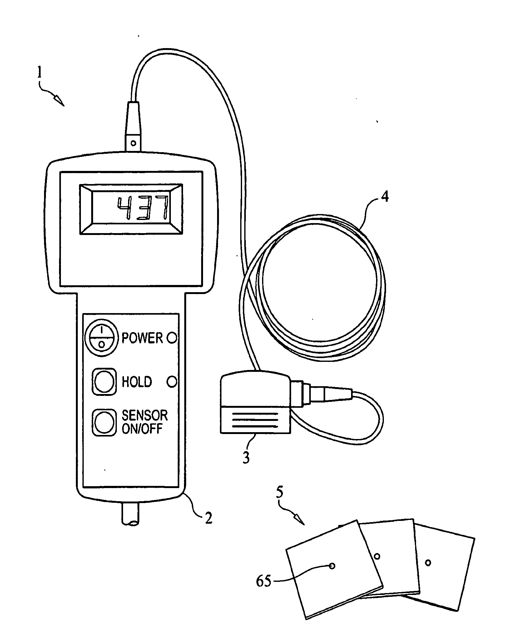
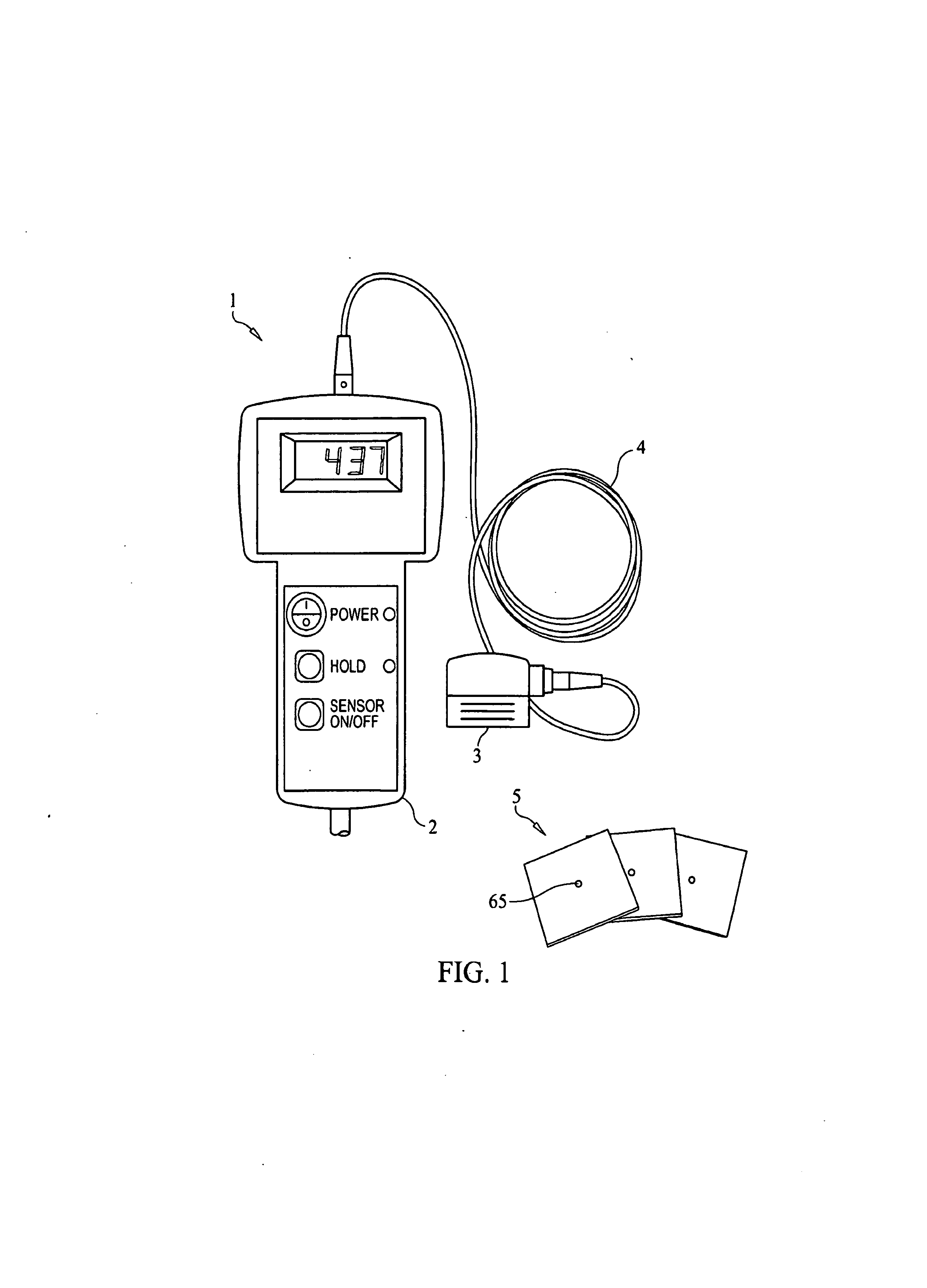
Nondestructive inspection apparatus and method for evaluating cold working effectiveness at fastener holes
a technology of non-destructive inspection and inspection apparatus, applied in the direction of magnetic property measurement, material magnetic variables, instruments, etc., can solve the problems of plastic deformation, interference expansion of the hole, and no longer considered to have adequate structural properties, etc., to achieve small impedance change, reduce signal loss and environmental noise, and easy measurement
- Summary
- Abstract
- Description
- Claims
- Application Information
AI Technical Summary
Benefits of technology
Problems solved by technology
Method used
Image

Examples
working example
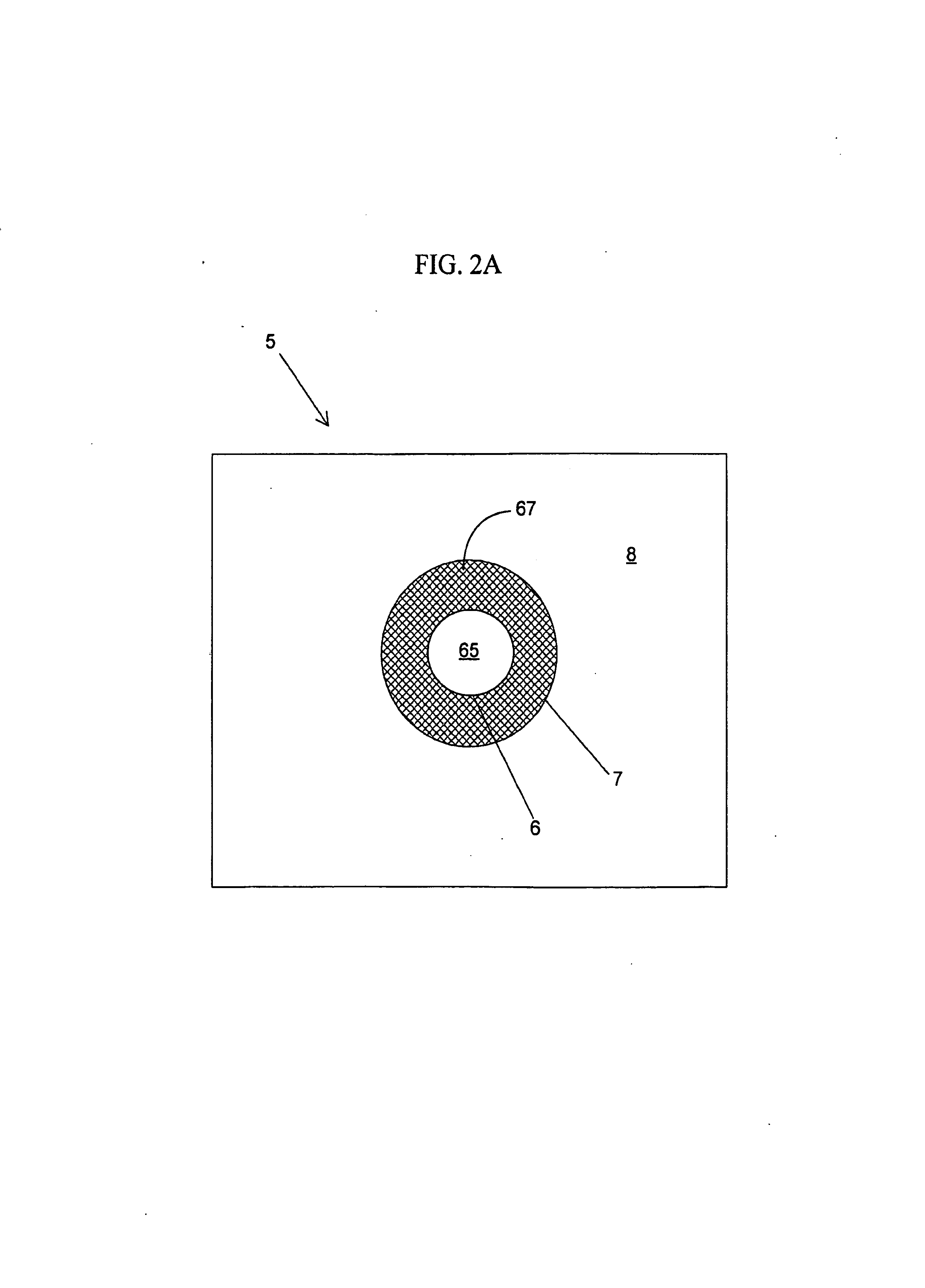
[0160]FIG. 10 presents data taken with a disclosed embodiment of analyzer 1 on cold worked holes and not cold worked holes. Each specimen was measured randomly five times. For the cold worked holes, the average detector reading 48 was around 4 for one specimen and around 5 for the other specimen. For the not cold worked holes, the average detector reading was around 0.50 for both specimens.
[0161]In summary, illustrative embodiments of the invention may be used to detect electrical conductivity changes in material adjacent to (around) cold worked holes and correlate the conductivity changes to a degree of cold work effectiveness. Other illustrative embodiments may be used to detect electrical conductivity changes in shot-peened material and correlate the conductivity changes to the degree or depth of shot-peening. Other illustrative embodiments may be used to detect electrical conductivity changes in a material wherein the surface of the material has been cold worked via any manufact...
PUM
| Property | Measurement | Unit |
|---|---|---|
| diameters | aaaaa | aaaaa |
| frequency | aaaaa | aaaaa |
| residual compressive stress | aaaaa | aaaaa |
Abstract
Description
Claims
Application Information