Resonator, filter, duplexer, and communication device

a communication device and filter technology, applied in the field of resonators, can solve the problems of reducing the characteristics of the resonator, the inability to solve the problem of the power loss due to the edge effect, and the penetration of magnetic fluxes into the resonator

Inactive Publication Date: 2002-11-26
MURATA MFG CO LTD
View PDF10 Cites 21 Cited by
  • Summary
  • Abstract
  • Description
  • Claims
  • Application Information

AI Technical Summary

Benefits of technology

According to another aspect of the present invention, there is provided a resonator including a substrate and a set of lines comprising a plurality of spiral lines, each of the lines being in a position of rotational symmetry with respect to another spiral line. With this arrangement, when each line is seen in a cross-sectional view taken in the direction of the radius-vector (radius) of the set of lines, at the right and left sides of each spiral line, a line defining a point in each line through which current having substantially the same amplitude and phase flows through all of the lines is arranged at substantially a constant distance from a central point of the set of lines, with the result that an edge effect can be effectively suppressed.

Problems solved by technology

In such a resonator, an inevitable problem is a reduction in its characteristics due to an inherent edge effect of a micro-strip line.
In this situation, since the current concentration occurs within a certain depth from the external surface of the line, even if the thickness of the line is increased, the problem of a power loss due to the edge effect cannot be solved.
With -this structure, magnetic fluxes penetrate into each conductor line from both sides of the line and interfere with each other.

Method used


Image

  • Resonator, filter, duplexer, and communication device
  • Resonator, filter, duplexer, and communication device
  • Resonator, filter, duplexer, and communication device

Examples


first embodiment

[Principle and FIGS. 1 to 10]

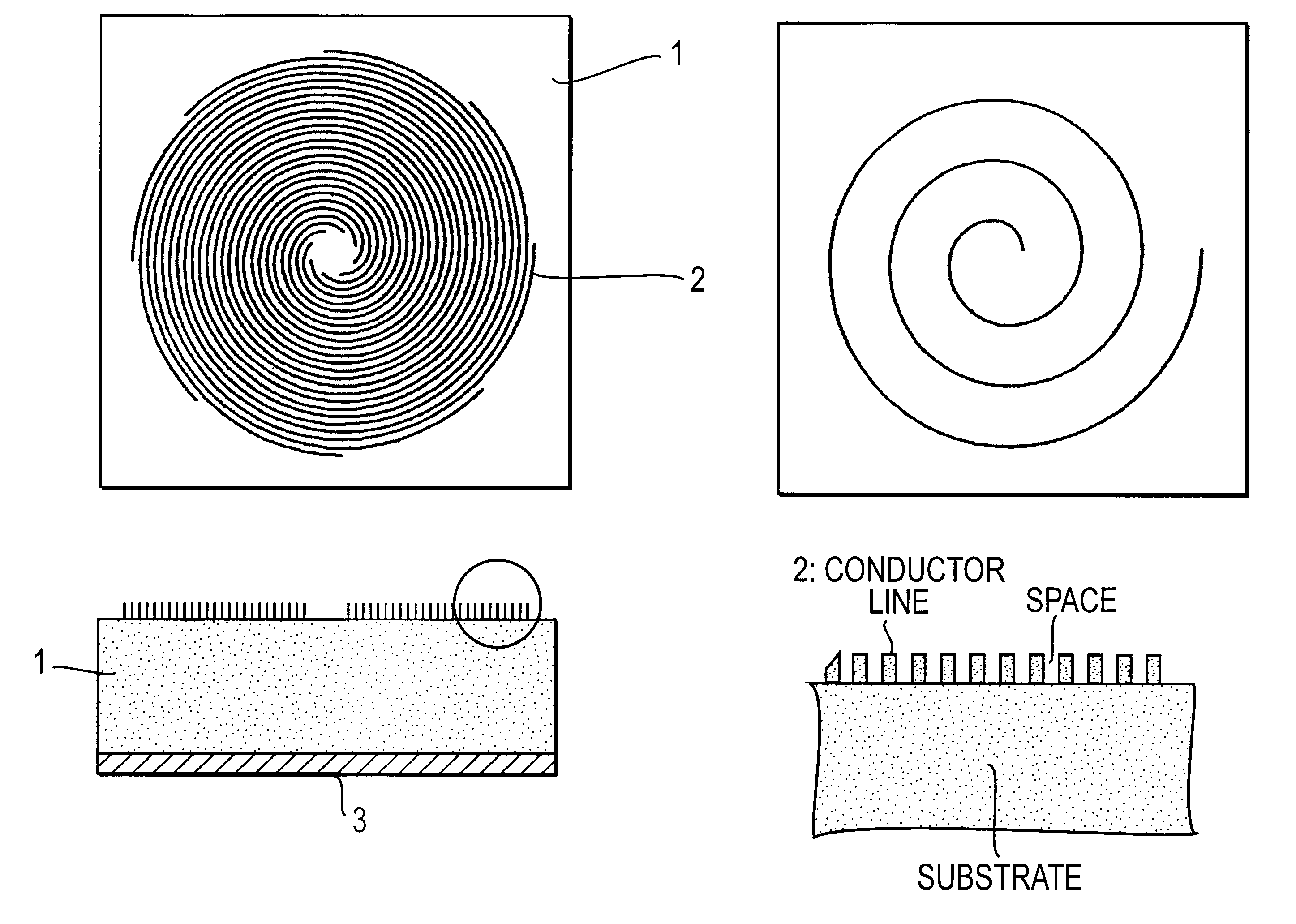
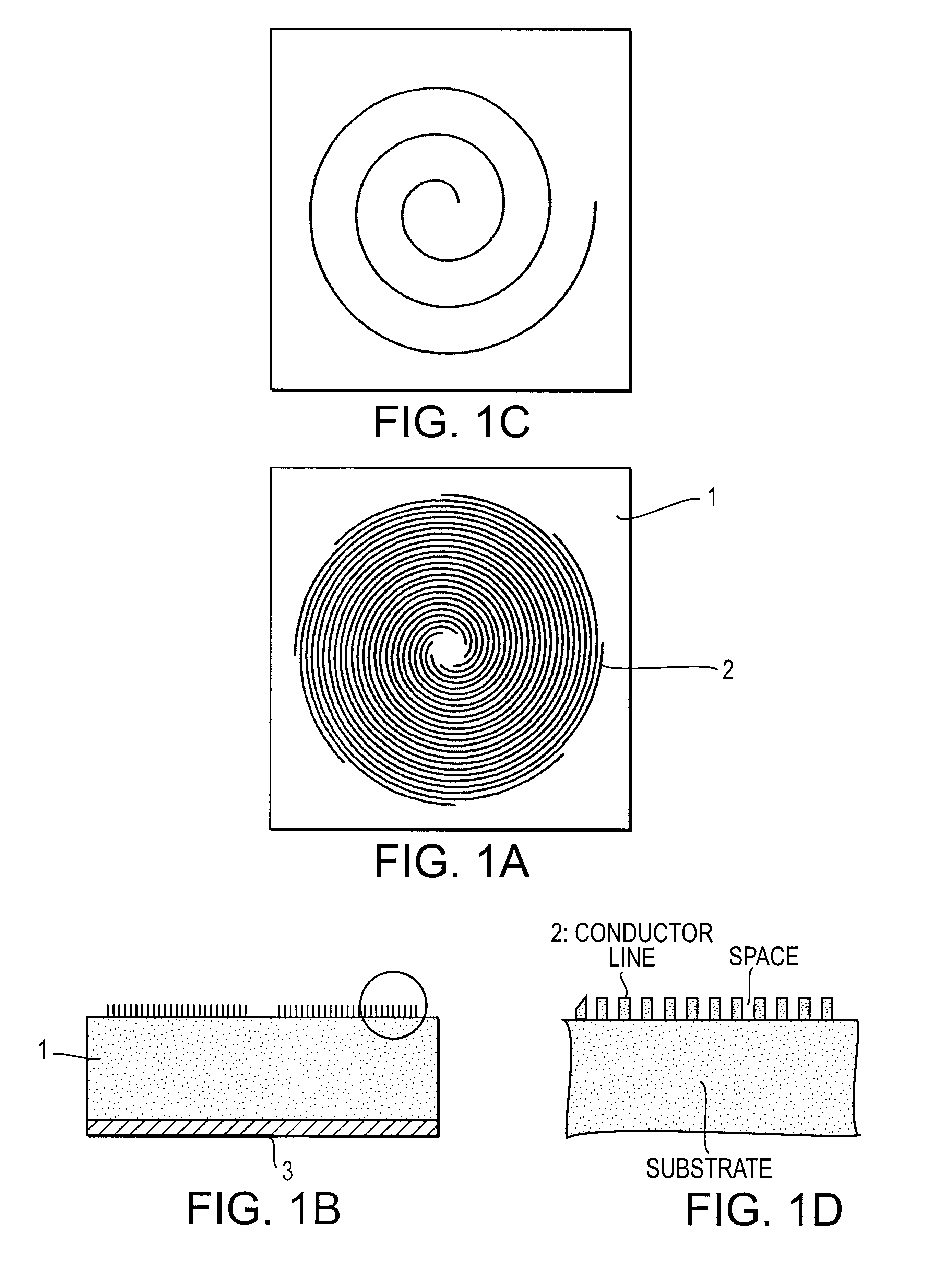
A ground electrode 3 is formed on the entire lower surface of a dielectric substrate 1. On the upper surface of the dielectric substrate 1, eight spiral lines 2 having the same shapes, both ends of the lines being open, are disposed in such a manner that the spiral lines do not cross each other. One end of each of the lines is disposed around an area where no lines are present, which is equivalent to the center of a spiral shown in FIG. 1A, as the central part of the substrate 1. Only one of the lines is indicated in FIG. 1C in order to simplify the illustration. Preferably, the width of the lines is substantially equal to the skin depth of the conductor material of the line.

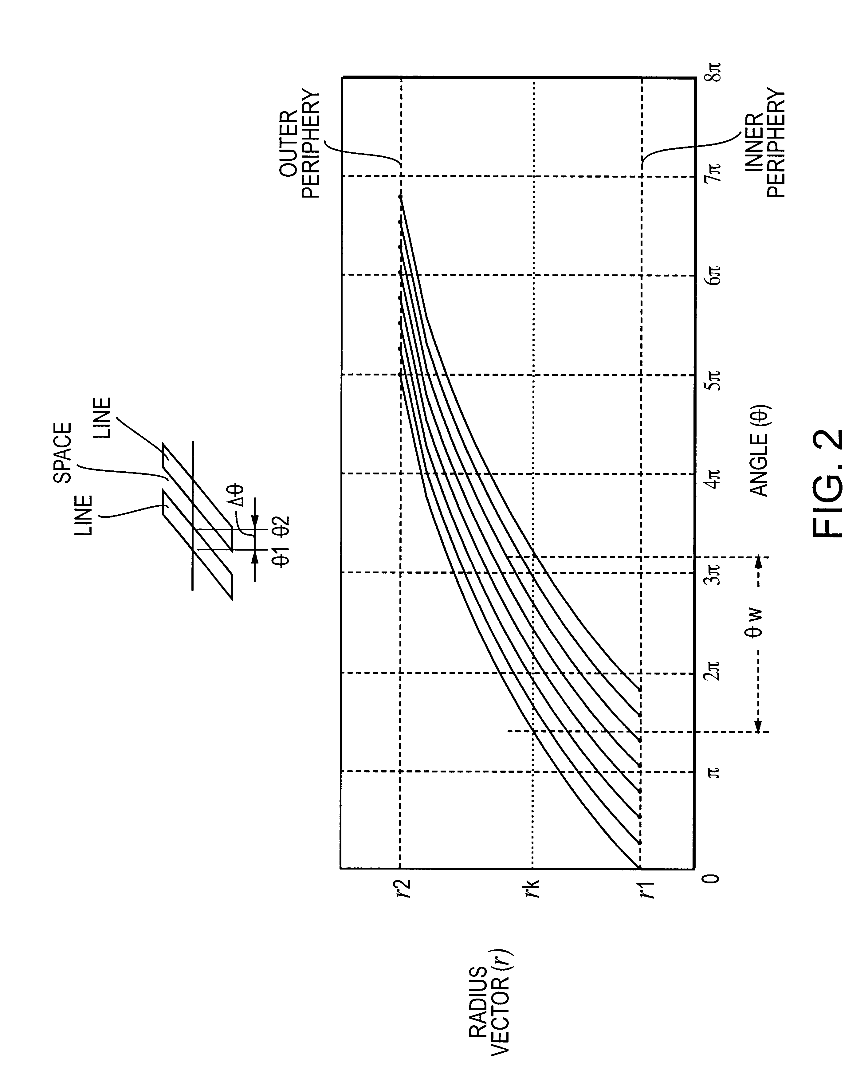
FIG. 2 is a graph in which the shapes of the eight lines shown in FIG. 1 are indicated by polar coordinates. In this case, a radius vector r.sub.1 of the inner peripheral end and a radius vector r.sub.2 of the outer peripheral end of each of the eight lines are fixed, and the positi...

second embodiment

[Second Embodiment]

In the second embodiment shown in FIGS. 11A to 11C, the inner peripheral end and outer peripheral end of each line 2 formed of a multi-spiral pattern on a substrate 1 are grounded to a ground electrode 3 via a through-hole. This allows the line to serve as a resonant line whose two ends are short-circuited. In this structure, since both ends of the resonant line are short-circuited, the resonator has a good shielding characteristic, by which it is not very susceptible to electromagnetic leakage to the outside and influences due to external electromagnetic fields.

third embodiment

[Third Embodiment]

In the third embodiment; shown in FIGS. 12A to 12C, the inner peripheral end of each line of a multi-spiral pattern is grounded to a ground electrode 3 via a through-hole. The outer peripheral end thereof is open. This arrangement permits the lines to serve as a 1 / 4-wavelength resonator. Since the resonator can provide a desired resonant frequency with, a short line length, the area occupied by the resonator on a substrate can be further reduced.


PUM


Abstract

A resonator can provide good loss characteristics by effectively suppressing power losses due to an edge effect. In addition, a filter, a duplexer, and a communication device incorporating the resonator are formed. In the resonator, a plurality of spiral lines are disposed on a surface of a dielectric substrate in such a manner that the inner and outer ends of the lines are aligned respectively along an inner periphery and an outer periphery which are centered around a central point on the substrate so that the lines do not cross each other. With this arrangement, the edge effect in the spiral lines is substantially canceled, by which power losses due to the edge effect can be effectively suppressed.

Description

1. Field of the InventionThe present invention relates to resonators, and more particularly, resonators formed by collecting a plurality of spiral lines, for use in microwave or millimeter-wave band communications. In addition, the invention relates to filters, duplexers, and communication devices incorporating the resonator.2. Description of the Related ArtAs an example of a resonator for use in microwave bands and millimeter-wave bands, a hairpin resonator is described in Japanese Unexamined Patent Publication No. 62-193302. The size of the hairpin resonator can be reduced more than that of a straight-line resonator.Additionally, another type of resonator capable of being made compact, a spiral resonator, is described in Japanese Unexamined Patent Publication No. 2-96402. In the spiral resonator, since a resonator line is formed of spiral shapes, a long resonant line can be arranged in a small area, with a resonant capacitor being provided as well, and a further reduction in the s...

Claims


Application Information

Patent Timeline
Patent Type & Authority Patents(United States)
IPC IPC(8): H01P1/203H01P1/213H01P7/08H01P1/20
CPCH01P1/20381H01P1/2135H01P7/082H01P7/08
Inventor HIDAKA, SEIJIOTA, MICHIAKIABE, SHINISHIKAWA, YOHEI
Owner MURATA MFG CO LTD
Why Eureka
Try Eureka