Method and apparatus for managing actinic intensity transients in a lithography mirror

a technology of actinic intensity and lithography mirror, which is applied in the field of lithography systems, can solve the problems of shorter wavelength light becoming absorbed by glass lenses, heat load on mirrors, and light not reaching silicon wafers, so as to reduce or eliminate the variation of image distortion, reduce or eliminate the effect of cold edge

Inactive Publication Date: 2006-02-07
ASML HLDG NV
View PDF6 Cites 21 Cited by
  • Summary
  • Abstract
  • Description
  • Claims
  • Application Information

AI Technical Summary

Benefits of technology

[0012]Maintaining the desired time-constant heat load on the mirror can reduce or eliminate variation in image distortion that occurs as a result of changes in actinic heat load on the lithography mirror. To mitigate the cold edge effect, the mirror can be divided into one or more zones with independent temperature control. This allows a constant additional heat load to be applied to a first zone while allowing the temperature in a second zone to be inversely modulated according to actinic heat load on the projection mirror. The flexibility of independent temperature control also allows a spatially constant total heat load.

Problems solved by technology

As chip manufacturers have been able to use shorter wavelengths of light, they have encountered a problem of the shorter wavelength light becoming absorbed by the glass lenses that are intended to focus the light.
Due to the absorption of the shorter wavelength light, the light fails to reach the silicon wafer.
The absorbed actinic light (i.e., energy generated from a light source such as an optical light source in a lithography tool) causes heat load on the mirror.
Too much heat can result in image distortion on the wafer.
Further, if heat load on the mirror is not maintained at a relatively constant level, variation in the amount of image distortion can occur.
A typical mirror is relatively large and has a high thermal mass with low thermal conductivity.
Due to the two above mentioned characteristics of the typical mirror in a lithography projection system, this conventional “control-by-heat-removal” method can be ineffective in environments with transient actinic heat loads.
As a result, the temperature of the mirror is not maintained at a constant over time and variation in distortion of the projected image occurs.

Method used


Image

  • Method and apparatus for managing actinic intensity transients in a lithography mirror
  • Method and apparatus for managing actinic intensity transients in a lithography mirror
  • Method and apparatus for managing actinic intensity transients in a lithography mirror

Examples


Embodiment Construction

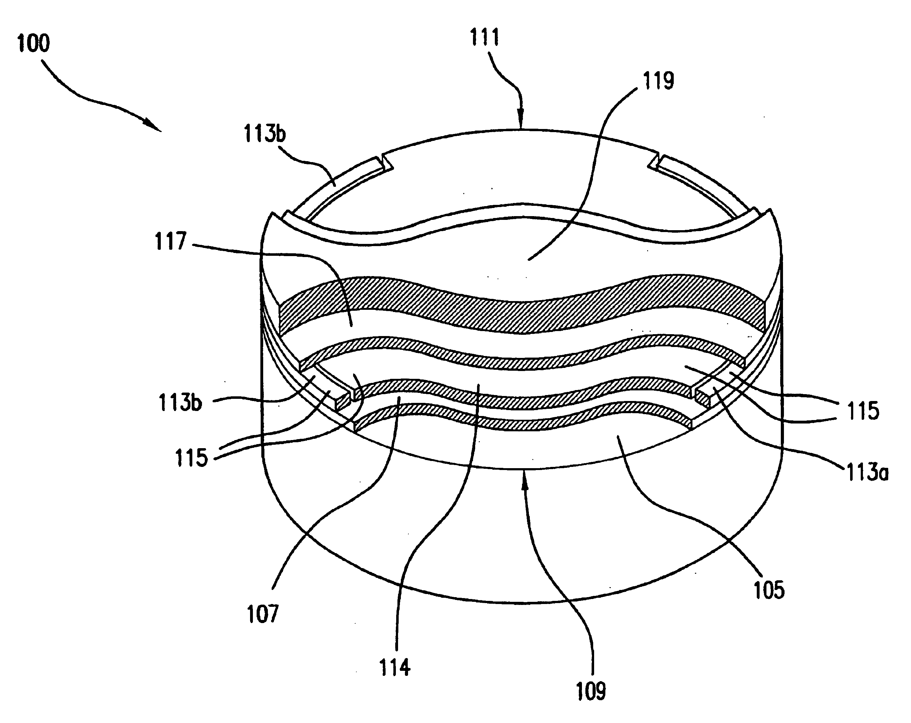
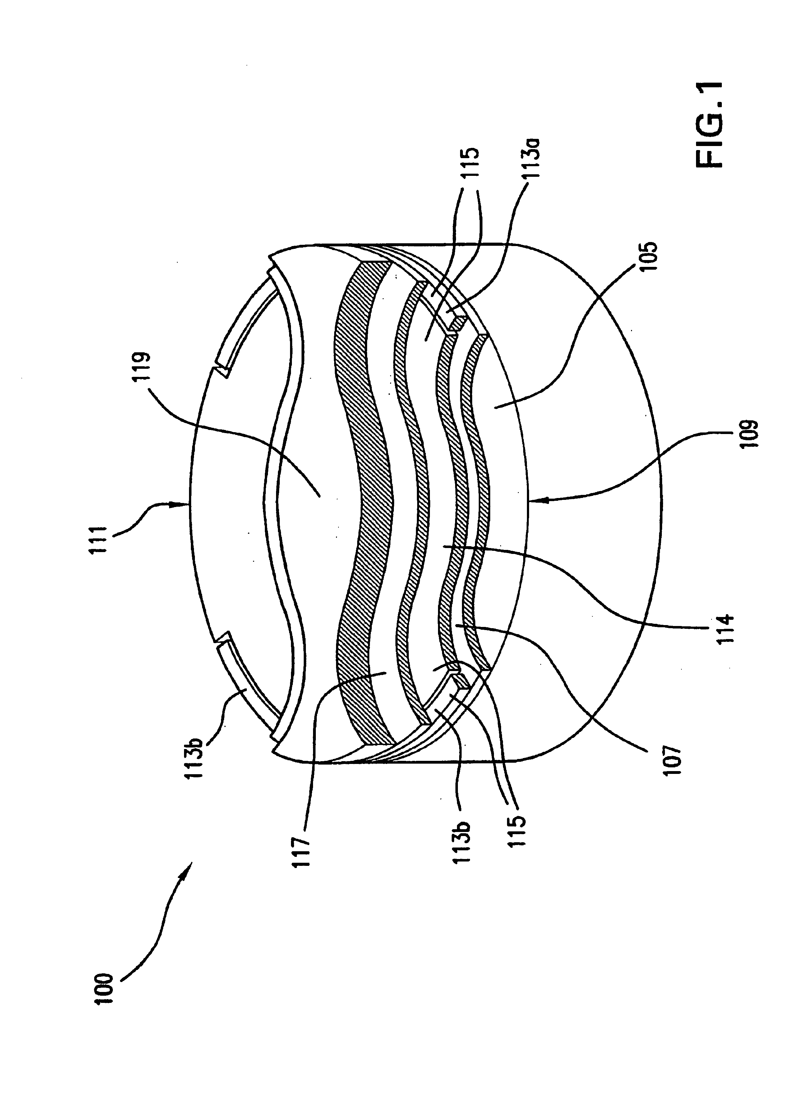
[0025]FIG. 1 illustrates a cross-sectional view of various layers and components of a lithography mirror 100 according to the present invention.

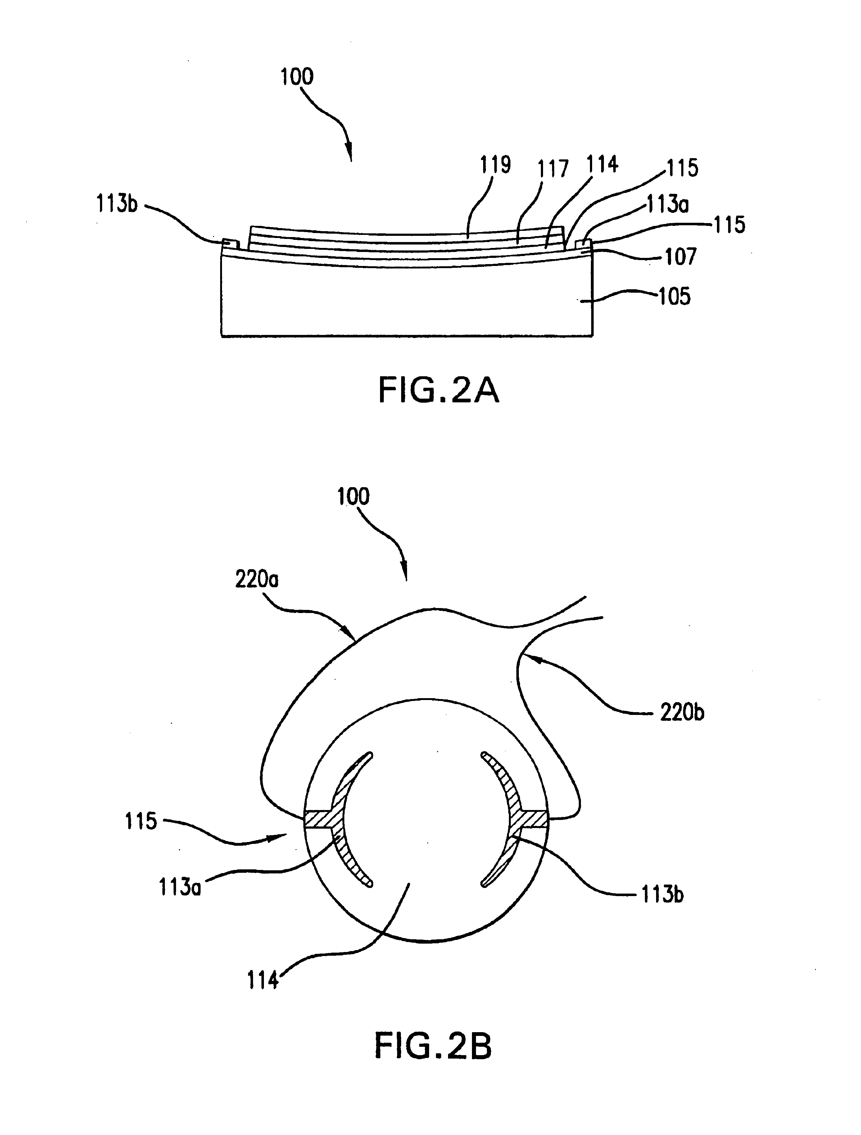
[0026]Lithography mirror 100 is composed of a mirror blank substrate 105, a resistive layer 107, a front edge 109, a rear edge 111, contacts 113 (e.g., electrodes) formed on resistive layer 107 for coupling a power supply (shown in FIG. 4) to resistive layer 107, a wiring layer 115, a polished layer 117, and a reflective layer 119.

[0027]Mirror blank substrate 105 is typically made of glass (e.g., low expansion glass, silicon, or quartz) and has a diameter-to-thickness ratio of approximately three to five. Mirror blank substrate 105 represents the basic structure of lithography mirror 100. The substrate should be machined and polished and have a near-zero Coefficient of Thermal Expansion (CTE), in accordance with standard industry practices. CTE is a thermodynamics term used to refer to the amount of increase in size of a solid object that oc...


PUM

PropertyMeasurementUnit
thicknessaaaaaaaaaa
poweraaaaaaaaaa
poweraaaaaaaaaa

Abstract

An apparatus and method of maintaining a time-constant heat load on a lithography mirror. The mirror includes a resistive layer formed on a substrate, contacts for coupling a power supply to the resistive layer, an insulating sublayer formed on the resistive layer, a polished layer formed on the insulating layer, and a reflective layer formed on the polished layer. The time-constant heat load on the lithography mirror is maintained by placing an additional electrical heat load on the mirror according to the actinic heat load transmitted by the mask. Maintaining the time-constant heat load can reduce or eliminate variation in image distortion that occurs as a result of changes in actinic heat load on the lithography mirror. Independent temperature control can be used to mitigate “cold-edge effect.”

Description

BACKGROUND OF THE INVENTION[0001]1. Field of the Invention[0002]The present invention relates generally to lithography systems. More particularly, the present invention relates to management of actinic heat load on mirrors in lithography systems.[0003]2. Background Art[0004]Lithography is a process used to create features on the surface of substrates. Such substrates can include those used in the manufacture of flat panel displays, circuit boards, various integrated circuits, and the like. A frequently used substrate for such applications is a semiconductor wafer. One skilled in the relevant art would recognize that the description herein would also apply to other types of substrates.[0005]During lithography, a wafer, which is disposed on a wafer stage, is exposed to an image projected onto the surface of the wafer by an exposure system located within a lithography system. The exposure system includes a reticle (also called a mask) for projecting the image onto the wafer.[0006]The r...

Claims


Application Information

Patent Timeline
Patent Type & Authority Patents(United States)
IPC IPC(8): G02B5/08G02B7/18G03F7/20H01L21/027
CPCG02B5/0891G02B7/181G02B7/1815G03F7/70958G03F7/70233G03F7/70891G03F7/702H01L21/027
Inventor DEL PUERTO, SANTIAGO
Owner ASML HLDG NV
Why Eureka
Try Eureka