
Method and apparatus for optimally tuning a circularly polarized patch antenna after installation

a patch antenna and optimal tuning technology, applied in the direction of antennas, antenna details, basic electric elements, etc., can solve the problems of unusable rf electronic devices, communication link loss or unreliability, and implementation of these antennas

Inactive Publication Date: 2004-01-20
CSR TECH INC
View PDF93 Cites 24 Cited by
  • Summary
  • Abstract
  • Description
  • Claims
  • Application Information

AI Technical Summary

Benefits of technology

"The present invention is about a method and apparatus for tuning a circularly polarized patch antenna to improve its performance and reduce variations in performance caused by environmental factors. The invention allows for easy tuning during manufacturing and in the field, and compensates for variations in the antenna caused by physical properties of the application using the antenna. The invention can also compensate for variations after the antenna is installed in the housing of the intended application. Overall, the invention improves the antenna's performance and reliability."

Problems solved by technology

Without a properly tuned antenna, or an antenna that properly uses the gain properties associated with such an antenna, the communications link can be lost or unreliable, making the RF electronic device unusable in certain situations.
Even with the attractiveness of the patch antenna size and ease of integration, there remain a number of difficulties with the implementation of these antennas.
However, as the antenna shrinks in size, the bandwidth of the antenna decreases.
With narrower bandwidth antennas, precise tuning of the antennas becomes necessary, or the antenna will not be able to receive or transmit the signal of interest.
Patch antennas, because of their thin nature, material makeup, and small size, are also more susceptible to changes in surrounding environment than other types of antennas.
As such, environmental effects, such as mistuning and bandwidth narrowing, can seriously degrade the performance of the antenna, and make implementing designs in a low cost product very difficult.
It is often necessary to have antenna manufacturers tune the antennas for a specific product, and the yield of this tuning may still cause a large amount of unit-to-unit variation.
Such an approach would not be acceptable for antennas that have already been installed in a device.
Such methods are not acceptable or directly applicable to conveniently tune a circularly polarized patch antenna.
Where satellites are communicating with terrestrial receivers, if a crossed polarization condition occurs, where the transmitted satellite power is rotated ninety degrees from the receive antenna polarization, no signal power is observed at the terrestrial receiver, which would render the terrestrial receiver useless in such a condition.
If a circularly polarized receive antenna is used in such a system, but the antenna is mistuned, most or all of the advantage of the extra power gain is lost.
Unfortunately small patches are very sensitive to manufacturing process, and are mistuned by materials placed around them.

Method used


Image

  • Method and apparatus for optimally tuning a circularly polarized patch antenna after installation
  • Method and apparatus for optimally tuning a circularly polarized patch antenna after installation
  • Method and apparatus for optimally tuning a circularly polarized patch antenna after installation

Examples


Embodiment Construction

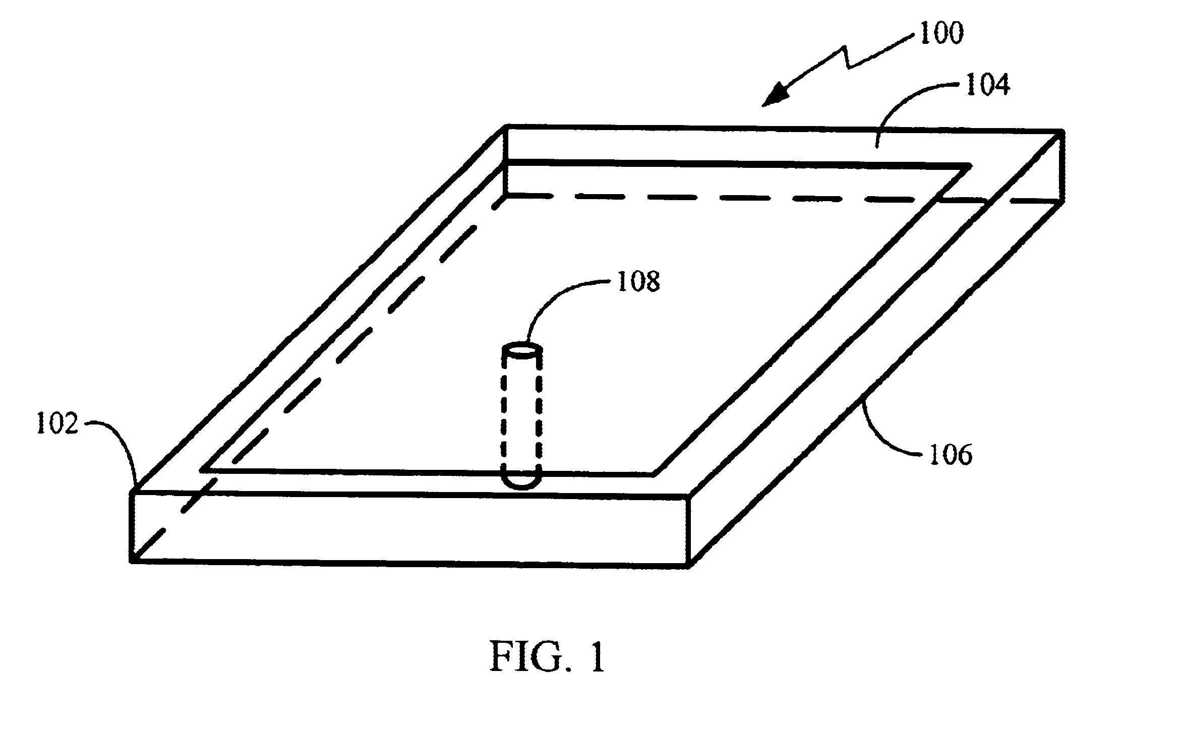
FIG. 1 illustrates a typical circularly polarized patch antenna. Antenna 100 comprises dielectric 102 with metal patch 104 deposited thereon. Bottom 106 of dielectric 102 is typically also metallized. Pin 108 is electrically connected to the metal patch 104, however, pin 108 is not electrically connected to the dielectric 102 or any metallization on the bottom 106. Pin 108 is typically metal, but can be any electrically conductive material.

In a typical application, the bottom 106 metalization is connected to an attached circuit ground, and pin 108 is connected to a low noise amplifier's input.

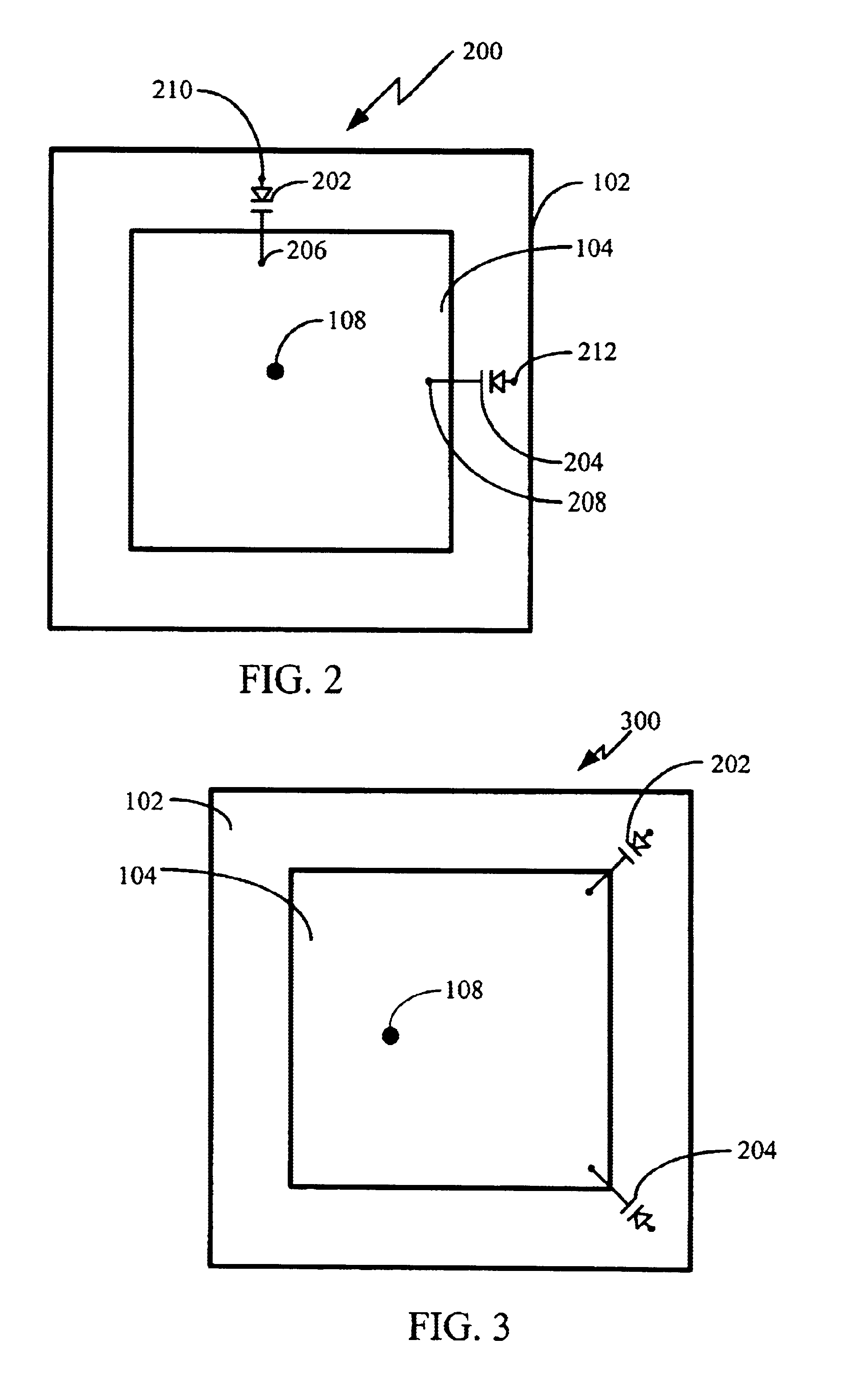
FIG. 2. illustrates a system in accordance with the present invention.

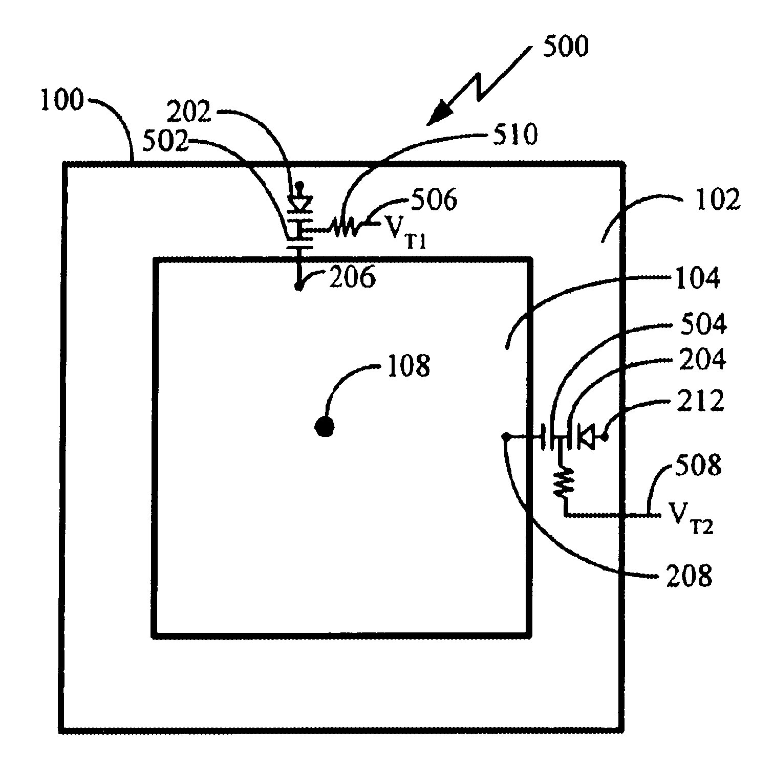
System 200 comprises varactors 202 and 204. Varactor 202 is electrically connected to metal patch 104 at point 206. Varactor 204 is electrically connected to metal patch 104 at point 208. Varactor 202 is electrically connected through the dielectric 102 to ground, which is typically the metallization on bottom 106, at point 2...


PUM


Abstract

The present invention provides methods and apparatuses for tuning a circularly polarized patch antenna to compensate for manufacturing tolerance variation, and to compensate for mistuning of the antenna due to the implementation of the product in which the antenna is used. Varactors are coupled to the metal patch portion of the antenna, and a dc voltage is applied to tune the antenna capacitance. The varactors can receive different voltages if desired.

Description

1. Field of the Invention.The present invention relates in general to radio frequency (RF) antennas, and, in particular, to dynamically optimizing the performance of a circularly polarized antenna.2. Description of the Related Art.The use of RF electronics has become commonplace in many facets of modem living, e.g., cellular telephones, satellite communications, television reception, computers, etc. Many of today's RF signals are transmitted in a wireless fashion, which requires the use of transmitting and receiving antennas to perform such tasks.As many RF devices become smaller, antenna design has become very important because of the antenna's important role in the communications link. Without a properly tuned antenna, or an antenna that properly uses the gain properties associated with such an antenna, the communications link can be lost or unreliable, making the RF electronic device unusable in certain situations. Many small RF devices use patch antennas because of their small s...

Claims


Application Information

Patent Timeline
Patent Type & Authority Patents(United States)
IPC IPC(8): H01Q9/04
CPCH01Q9/0428H01Q9/0442
Inventor MCCONNELL, RICHARD JOSEPH
Owner CSR TECH INC
Learn More