Microfluidic system and methods

Inactive Publication Date: 2009-06-04
SCIEX
View PDF9 Cites 74 Cited by
  • Summary
  • Abstract
  • Description
  • Claims
  • Application Information

AI Technical Summary

Benefits of technology

[0051]Fluorous (e.g. Perfluorocarbon) solvents typically possess high densities (2.5 times those of hydrocarbon analogues), have low dielectric constants and a lower polarity than saturated alkanes. This is due to the low surface potential and the compact electron distribution of these fluorocarbon solvents.
[0052]Carbon atoms form very strong bonds to fluorine and, as a result, fl

Problems solved by technology

However, isolated target assays do not allow investigations of toxicity to be carried out and they generally provide no information on the effect a chemical entity would have on a living cell.
However, as the cell is a complex system, it is more difficult to collect and interpret the data.
Such assays are generally incompatible with systems in which the assay components are present in flow-based systems.
In general, efforts to reduce reagent volumes below 10 μL per well have not been successful, particularly in the lead optimisation stage of the drug discovery process, and in consequence many assays are still performed in 96 and 384 well MTPs.
Unfortunately, the higher density MTPs produce an increase in the surface area:volume ratio such that incorrect data may be produced due to non-specific sequestration of one or more components (such as the drug target) by the MTP surface.
However, to date, there are no commercial microfluidic systems available that are able to compete with the MTP approach to performing biological assays.
However, the effects of the Taylor dispersion are generally considered inconsequential in comparison to the absorption of reaction or assay components to the surface of the channel through which the aqueous assay medium flows.
The requirement f

Method used


Image

  • Microfluidic system and methods
  • Microfluidic system and methods
  • Microfluidic system and methods

Examples


example

Coating Of The Glass Microchannel Surface

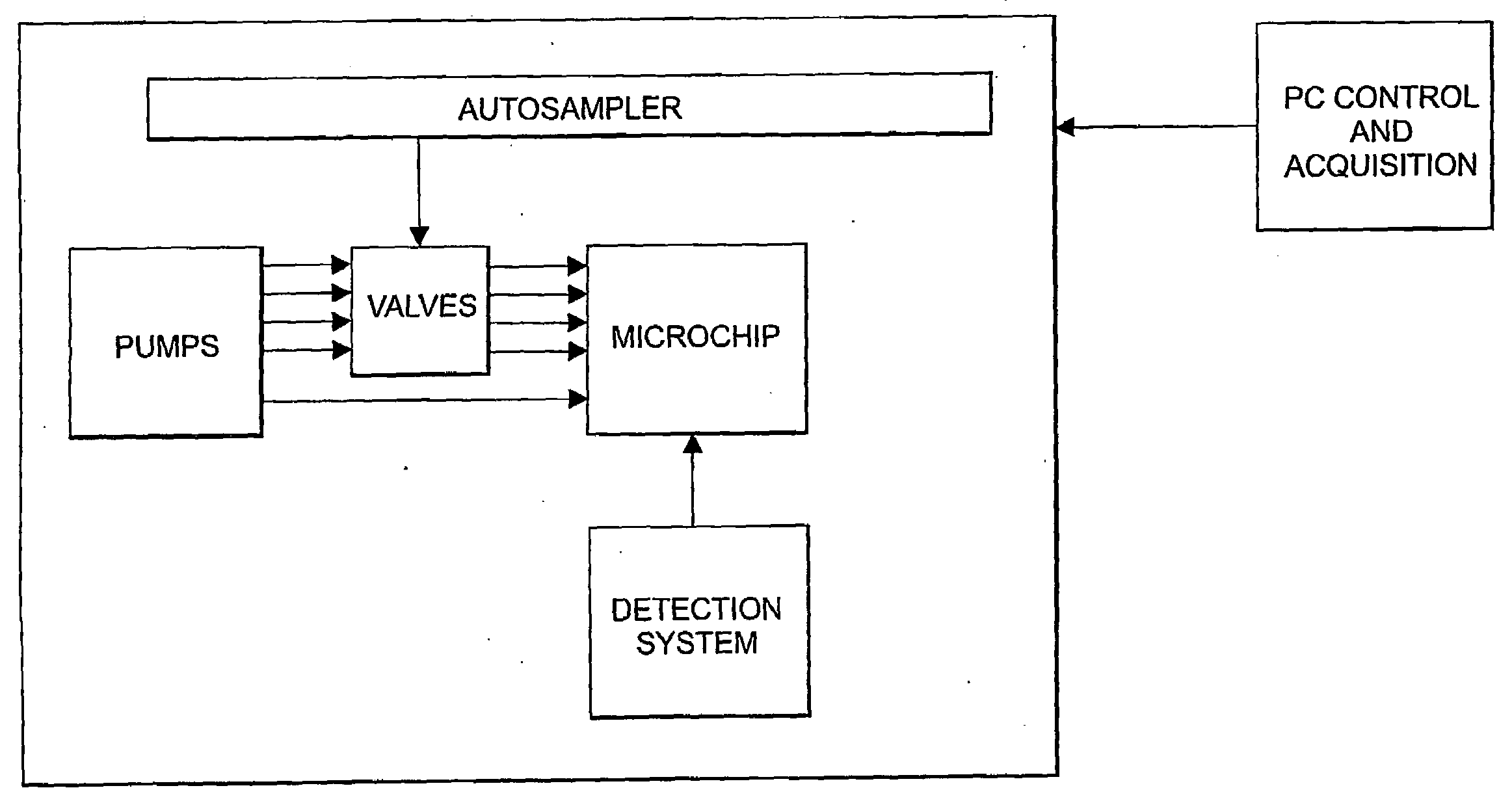
[0137]For dervatization of the internal surface of the glass microchannels, glass microchannels (Micronit microfluidics bv) were coupled up to syringes (volume 100 uL, model 81075, Hamilton company) via polyimide-coated fused silica capillaries (Polymicro Technologies) with outer diameter of 375 urn and internal diameter of 100 um. Capillaries were connected to the syringe needle via an in-line, Microtight (Registered Trade Mark) capillary connector (Upchurch scientific) and were connected to the glass microchannel chip via a bespoke connector block (FIG. 11) using Nanoport (Registered Trade Mark) connector adaptors (Upchurch Scientific). Fluid was pumped using stepper motor-based syringe pumps (model 33, Harvard Apparatus Company).

[0138]In one embodiment, the internal surface of glass microchannels (Micronit Microfluidics bv), which had internal dimensions of 20 um depth and 50 um, 70 um and 120 um width, were derivatized with 1H, 1H, 2H, 2H...


PUM


Abstract

A microfluidic system comprising: at least one microfluidic channel, the inner surface of which is fluorinated or fluorous; and a pump for supplying a flow of an aqueous medium containing chemical reagents or assay components to said microfluidic channel. Preferably, the apparatus further comprises a supply of a non-aqueous medium which is compatible with the surface of the microfluidic channel but immiscible with the aqueous medium, such as a perfluorocarbon solvent, for forming a sheath around the flowing aqueous medium whereby the aqueous medium is suspended away from the surface of the microfluidic channel. Also provided are methods for carrying out a chemical reaction or a biological assay in the microfluidic systems of the subject matter disclosed herein.

Description

CROSS-REFERENCE TO RELATED APPLICATIONS[0001]This application claims the benefit of U.S. Patent Application Ser. No. 60 / 707,384, filed Aug. 11, 2005, the disclosure of which is incorporated herein by reference in its entirety. The disclosures of the following U.S. Provisional Applications, commonly owned and simultaneously filed Aug. 11, 2005, are all incorporated by reference in their entirety: U.S. Provisional Application entitled MICROFLUIDIC APPARATUS AND METHOD FOR SAMPLE PREPARATION AND ANALYSIS, U.S. Provisional Application No. 60 / 707,373 (Attorney Docket No. 447 / 99 / 2 / 1); U.S. Provisional Application entitled APPARATUS AND METHOD FOR HANDLING FLUIDS AT NANO-SCALE RATES, U.S. Provisional Application No. 60 / 707,421 (Attorney Docket No. 447 / 99 / 2 / 2); U.S. Provisional Application entitled MICROFLUIDIC BASED APPARATUS AND METHOD FOR THERMAL REGULATION AND NOISE REDUCTION, U.S. Provisional Application No. 60 / 707,330 (Attorney Docket No. 447 / 99 / 2 / 3); U.S. Provisional Application enti...

Claims


Application Information

Patent Timeline
IPC IPC(8): G01N21/64
CPCB01L3/50273B01L3/502738B01L3/502776B01L3/502784B01L2200/0636B01L2400/0487B01L2200/12B01L2300/0654B01L2300/0867B01L2300/165B01L2200/0673
Inventor WARRINGTON, BRIAN HERBERTHOYLE, CHRISTOPHER KEVINPELL, THERESA JANEPARDOE, DAVID ALAN
Owner SCIEX
Why Eureka
Try Eureka