
Image-based determination of co and co2 concentrations in vehicle exhaust gas emissions

a technology of co and co2 concentration and vehicle exhaust gas, which is applied in the direction of instruments, television systems, structural/machine measurement, etc., can solve the problems of less efficient and likely mechanical problems of gross pollutant vehicles

Active Publication Date: 2013-07-18
CONDUENT BUSINESS SERVICES LLC
View PDF5 Cites 57 Cited by
  • Summary
  • Abstract
  • Description
  • Claims
  • Application Information

AI Technical Summary

Benefits of technology

The patent describes a system and method for using a camera to capture images of a vehicle's exhaust gases and determine the concentration levels of CO and CO2. This information can be used to determine if the vehicle is a gross polluter, which is when the levels of CO and CO2 are at least twice the standard for that vehicle. The system is versatile and can be used in a remote sensing, non-cooperative environment, which makes it easier to measure emissions from vehicles.

Problems solved by technology

A gross pollutant vehicle is usually less efficient and is likely to have mechanical issues.

Method used


Image

  • Image-based determination of co and co2 concentrations in vehicle exhaust gas emissions
  • Image-based determination of co and co2 concentrations in vehicle exhaust gas emissions
  • Image-based determination of co and co2 concentrations in vehicle exhaust gas emissions

Examples


first embodiment

Flow Diagram of a First Embodiment

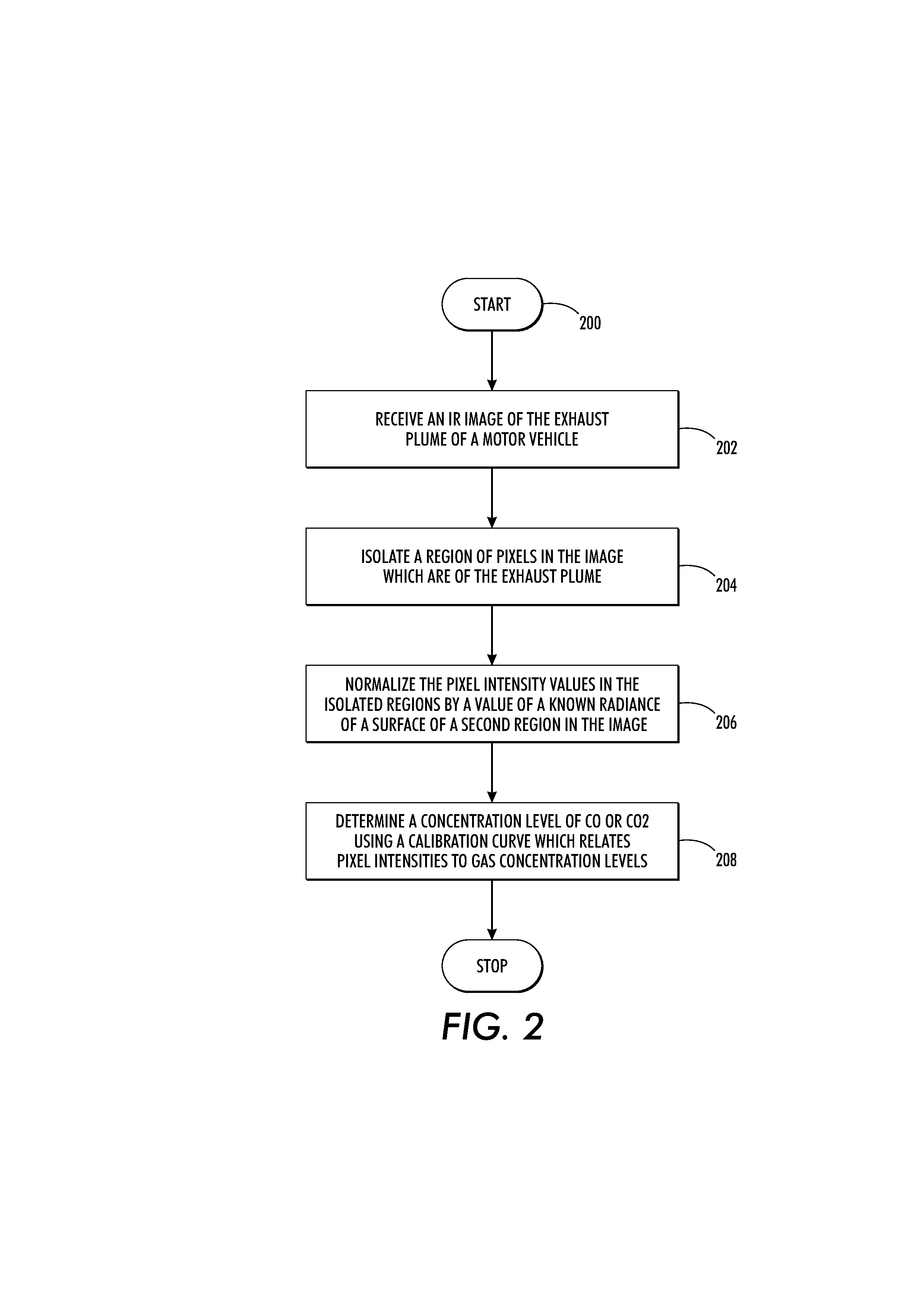
[0042]Reference is now being made to the flow diagram of FIG. 2 which illustrates one example embodiment of the present method for image-based determination of CO and CO2 concentrations in the vehicle's exhaust gas in an emissions testing environment. Flow processing begins at step 200 and immediately proceeds to step 202.

[0043]At step 202, receive at least one IR image of an exhaust plume of a motor vehicle. The received images have been captured using a mid-wave infrared camera having at least one optical filter tuned to the infrared absorption band of an emissions gas comprising at least one of: CO and CO2.

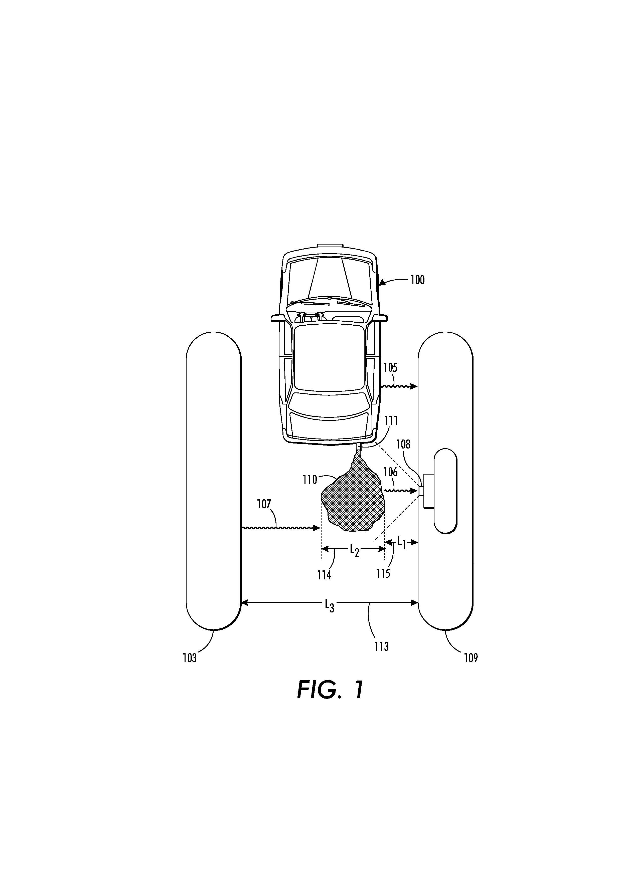
[0044]At step 204, isolate a region of pixels of the exhaust plume in the image. FIG. 3 shows an example infrared image 300 of the exhaust plume 110 of the vehicle 100 of FIG. 1 wherein a first region 302 containing pixels of the exhaust plume has been isolated.

[0045]At step 206, normalize the intensity values of pixels in the isolated region b...

second embodiment

Flow Diagram of a Second Embodiment

[0048]Reference is now being made to the flow diagram of FIG. 4 which illustrates one embodiment of using a vehicle's electronic tag to facilitate testing of the vehicle's exhaust emissions. Flow begins at step 400 and processing immediately proceeds to step 402.

[0049]At step 402, a sensor is used to query an electronic tag fixed to a motor vehicle as the vehicle passes through a lane of an emissions testing structure. One such structure is shown and discussed with respect to FIG. 1.

[0050]At step 404, the vehicle's electronic tag responds with information about the vehicle. In one embodiment, information provided by the electronic tag in response to the sensors query includes the vehicle's license plate number, the vehicle's year / make / model, the vehicle's registration information, a date of the vehicle's last emissions test, and the vehicle owner's name and address. In another embodiment, the electronic tag responds with an account identification w...


PUM


Abstract

What is disclosed is a system and method for image-based determination of concentration of CO and CO2 in a vehicle's exhaust gas in an emissions testing environment. In one embodiment, the present method involves receiving an IR image of the exhaust plume of a motor vehicle intended to be tested for CO and CO2 concentrations. The IR image has been captured using a mid-wave infrared camera with at least one optical filter tuned to the infrared absorption band of CO and CO2. The images are pre-processed to isolate pixels which contain the exhaust plume. The intensity values of pixels in those isolated regions are normalized and concentrations of CO and CO2 are determined via a calibration curve which relates pixel intensities to concentrations. The concentrations are compared to an emissions standard set for the vehicle to determine whether the vehicle is a gross polluter.

Description

CROSS REFERENCE TO RELATED APPLICATION[0001]The present patent application is a continuation-in-part of commonly owned and co-pending U.S. patent application Ser. No. 13 / 352,683 entitled: “Vehicle Emissions Testing And Toll Collection System”, by Cardoso et al., which is incorporated herein in its entirety by reference.TECHNICAL FIELD[0002]The present invention is directed to systems which use an infrared camera with filters tuned to the infrared absorption band of CO and CO2 molecules to capture images of the exhaust of a motor vehicle and to methods for analyzing those images to determine concentrations of CO and CO2 in the vehicle's exhaust gas emissions.BACKGROUND[0003]Government regulations on car emissions require an approved test facility to monitor car emissions. Emissions testing is typically performed every one or two years depending on the State regulations regarding testing schedules. Testing is usually performed as a requisite to vehicle registration. An estimated two b...

Claims


Application Information

Patent Timeline
IPC IPC(8): G06K9/62G08B21/00H04N7/18
CPCG01M15/108
Inventor CARDOSO, GEORGE CUNHAMESTHA, LALIT KESHAV
Owner CONDUENT BUSINESS SERVICES LLC
Learn More