Check patentability & draft patents in minutes with Patsnap Eureka AI!

Device for surveying surround of working machine

a technology for working machines and surrounds, which is applied in soil shifting machines/dredgers, television systems, transportation and packaging, etc., can solve the problems of limited viewing angle of cameras, low operability of image switching operations, and operator time-consuming to perform image switching operations. achieve the effect of simple operation

Inactive Publication Date: 2013-07-18
NIHON KENKI CO LTD
View PDF4 Cites 93 Cited by
  • Summary
  • Abstract
  • Description
  • Claims
  • Application Information

AI Technical Summary

Benefits of technology

The patent describes a system that allows a camera to capture images of a working machine and then convert them to an overview image. The overview image can then be displayed alongside the camera images, allowing an operator to easily monitor the machine's surroundings. The system is designed to provide accurate and useful information with minimal effort.

Problems solved by technology

The camera is fixed to the upper swiveling body, and the range of the viewing angle of the camera is limited.
However, since a plurality of cameras are installed, the operator may have to operate the selector switch a plurality of times before a desired image is displayed, and it may take time for the operator to perform an image switching operation.
Thus, the operability of this image switching operation is not high.
Sometimes, it is difficult to determine exact distances from camera images.
If a working person exists near the working machine or if there is an obstacle, such as a structure, near the working machine, it may be difficult to determine exactly, only from camera images, whether the working machine will contact the working person or the structure when operating the upper swiveling body.
Additionally, when backward moving the base carrier, it may be difficult to accurately understand to which extent the working machine is approaching the working person or the structure, or to recognize the presence or the position of a depression, such as a ditch.
In this case, if the operator uses only camera images for conducting surveillance around the working machine, although the operator can recognize the presence or the absence of an object to be avoided of a type described above and the shape and the size thereof, it may be difficult to determine an exact distance from the working machine to such an object.

Method used


Image

  • Device for surveying surround of working machine
  • Device for surveying surround of working machine
  • Device for surveying surround of working machine

Examples


Embodiment Construction

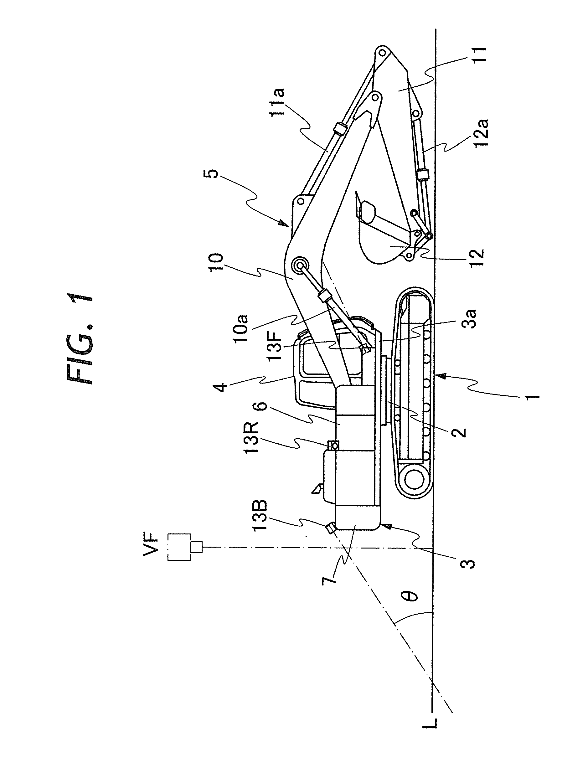
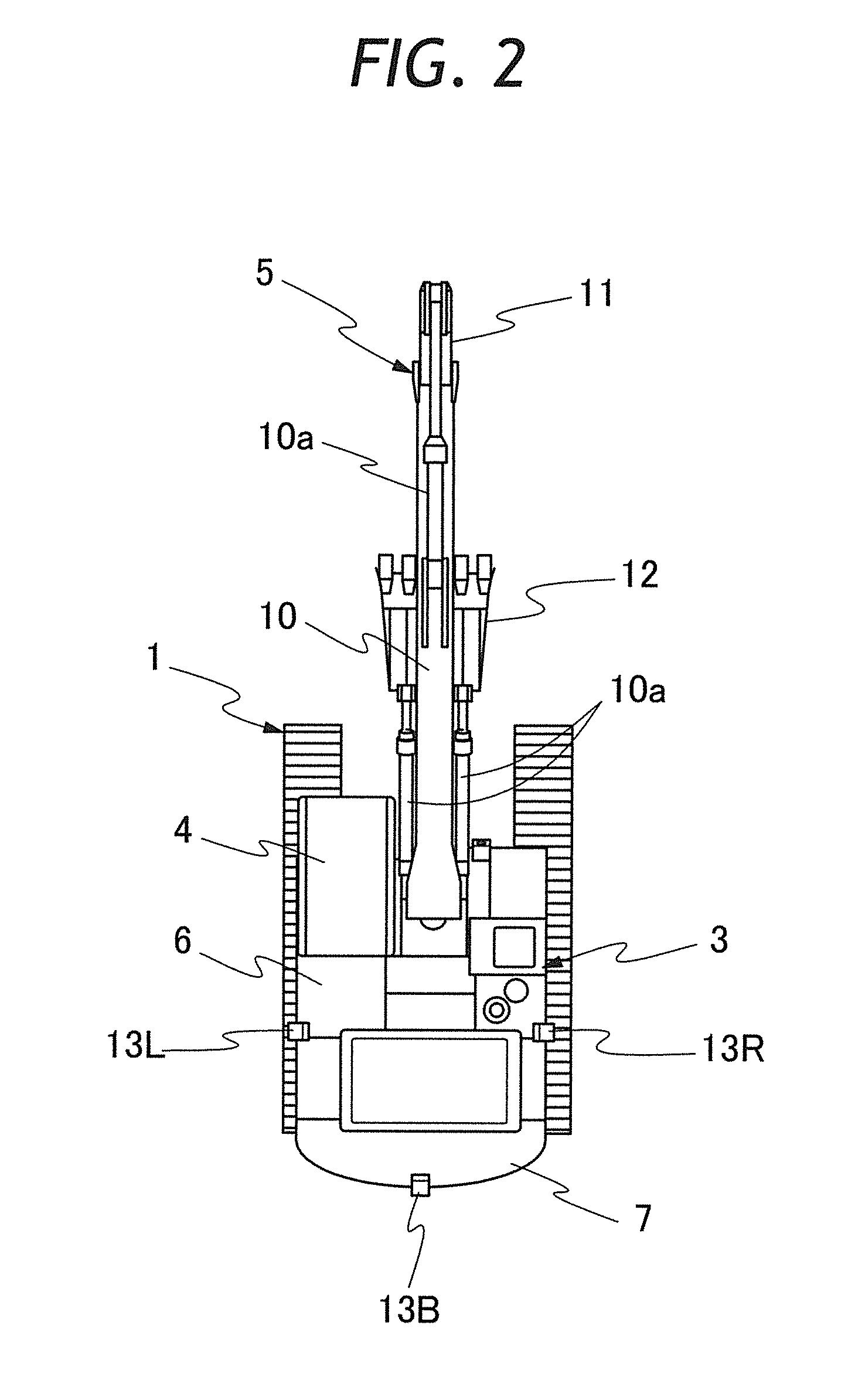
[0039]An embodiment of the present invention will be described hereinafter with reference to the drawings. The configuration of a hydraulic excavator, which is an example of a working machine, is shown in FIGS. 1 and 2. In the drawings, reference numeral 1 denotes a base carrier having a crawler carriage, and an upper swiveling body 3 is provided on the base carrier 1 by way of a swiveling unit 2.

[0040]In the upper swiveling body 3, a cabin 4 on which an operator sits and operates the machine is installed, and a working mechanism 5 for conducing work, for example, to excavate landside, is also installed. The working mechanism 5 is located on the right side of the cabin 4 and at a position substantially parallel with the cabin 4. Additionally, in the upper swiveling body 3, a machine housing 6, etc. is provided at a position at the back of the cabin 4 and the working mechanism 5, and a counterweight 7 is provided at the tail end.

[0041]The working mechanism 5 is a excavating mechanism...


PUM


Abstract

A back camera 13B, left-side and right-side cameras 13L and 13R, and a front camera 13F are provided on an upper swiveling body 3. By converting viewpoints of camera images obtained by the cameras 13B, 13L, and 13R, individual over view images are generated and are combined with one another to form a surveillance panorama image disposed around a display character 21. The surveillance panorama image is displayed, together with a camera image, which is an image obtained by the front camera 13F, in an image display section 20a of a monitor 20. By appropriately operating switches SW1 through SW5 provided in an operation panel section 20b, a camera image which has not been converted into one of the individual over view images is displayed in an enlarged state.

Description

TECHNICAL FIELD[0001]The present invention relates to a device for surveying surround of a working machine, such as a hydraulic excavator, etc., to survey for ensuring for the purpose of safety, etc. for conducting work by using the working machine.BACKGROUND ART[0002]A hydraulic excavator, which is an example of working machines, is a self-propelled working machine, and includes a base carrier having a crawler or wheel carriage. An upper swiveling body is installed on the base carrier by way of a swiveling unit. The upper swiveling body is provided with a working mechanism that conducts work, such as excavating landside. The working mechanism includes a boom which is connected to the upper swiveling body such that the boom is able to move up and down, and an arm attached to the forward end of the boom such that the arm is vertically pivotable. A bucket for conducting work, such as excavating landside, is attached, as a front attachment, to the forward end of the arm by way of a lin...

Claims


Application Information

Patent Timeline
Patent Type & Authority Applications(United States)
IPC IPC(8): H04N7/18
CPCH04N7/181E02F9/261H04N7/18B60R1/00E02F9/24E02F9/26
Inventor ISHIMOTO, HIDEFUMI
Owner NIHON KENKI CO LTD
Features
  • R&D
  • Intellectual Property
  • Life Sciences
  • Materials
  • Tech Scout
  • Unparalleled Data Quality
  • Higher Quality Content
  • 60% Fewer Hallucinations
Learn More