
Projection type image display apparatus

a technology of projection type and image display, which is applied in the direction of projectors, color television details, instruments, etc., can solve the problems of not being able to easily replace a light source, and other light sources arranged behind the removable light source cannot be easily removed, so as to achieve the effect of easy and efficient removal and replacemen

Inactive Publication Date: 2013-07-18
PANASONIC INTELLECTUAL PROPERTY MANAGEMENT CO LTD
View PDF32 Cites 7 Cited by
  • Summary
  • Abstract
  • Description
  • Claims
  • Application Information

AI Technical Summary

Benefits of technology

The present invention is about a projection type image display apparatus that allows easy and efficient replacement of multiple light sources. The technical effect of this invention is that users can easily and efficiently remove and replace one or all of the multiple light sources, which improves the flexibility and usefulness of the display apparatus.

Problems solved by technology

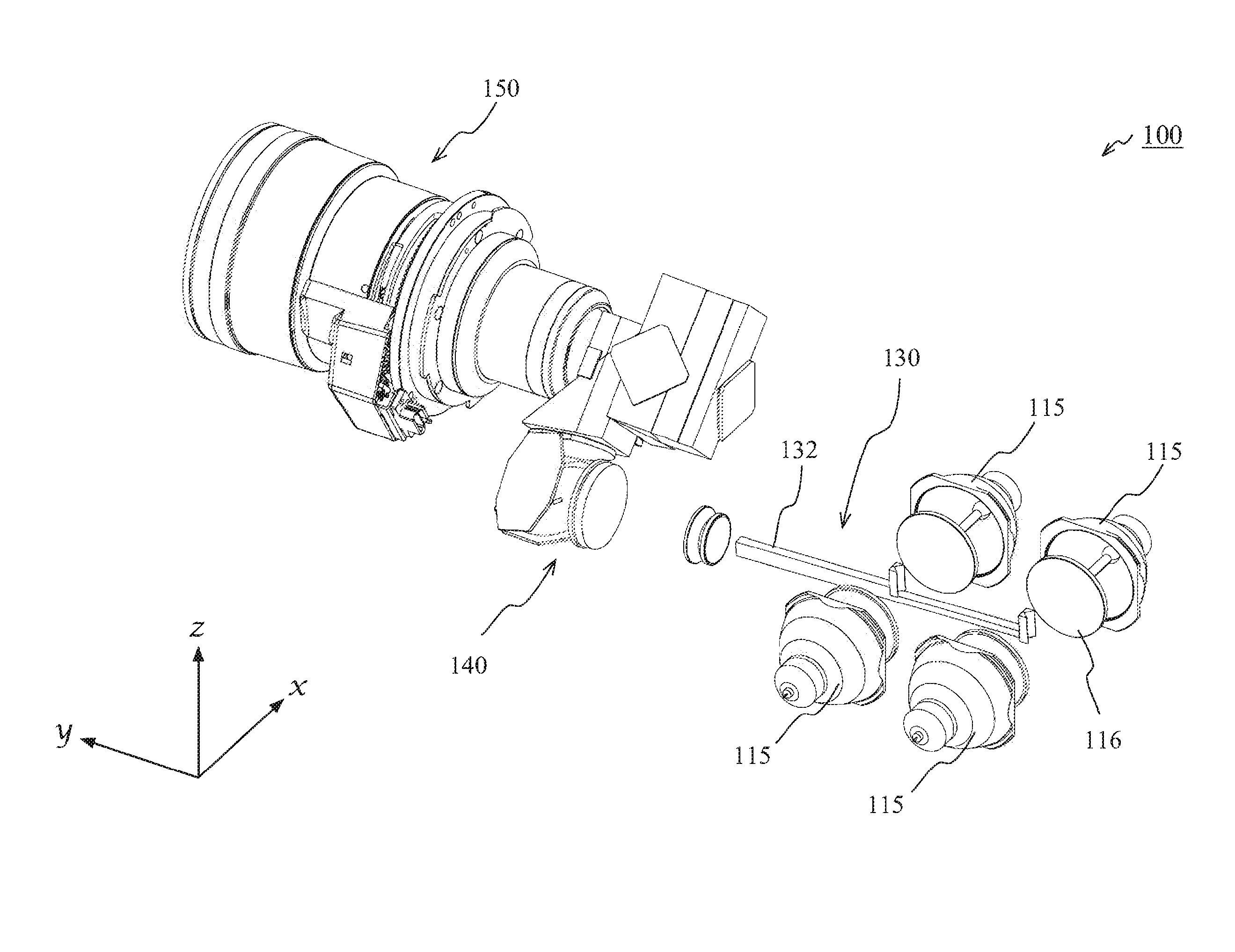
Therefore, when the technology disclosed in Patent Literature 1 is simply applied to a projection type image display apparatus including multiple light sources, even if it is possible to remove an outer mostly arranged light source from a lateral surface of the case, other light sources arranged behind the removable light source cannot be easily removed.
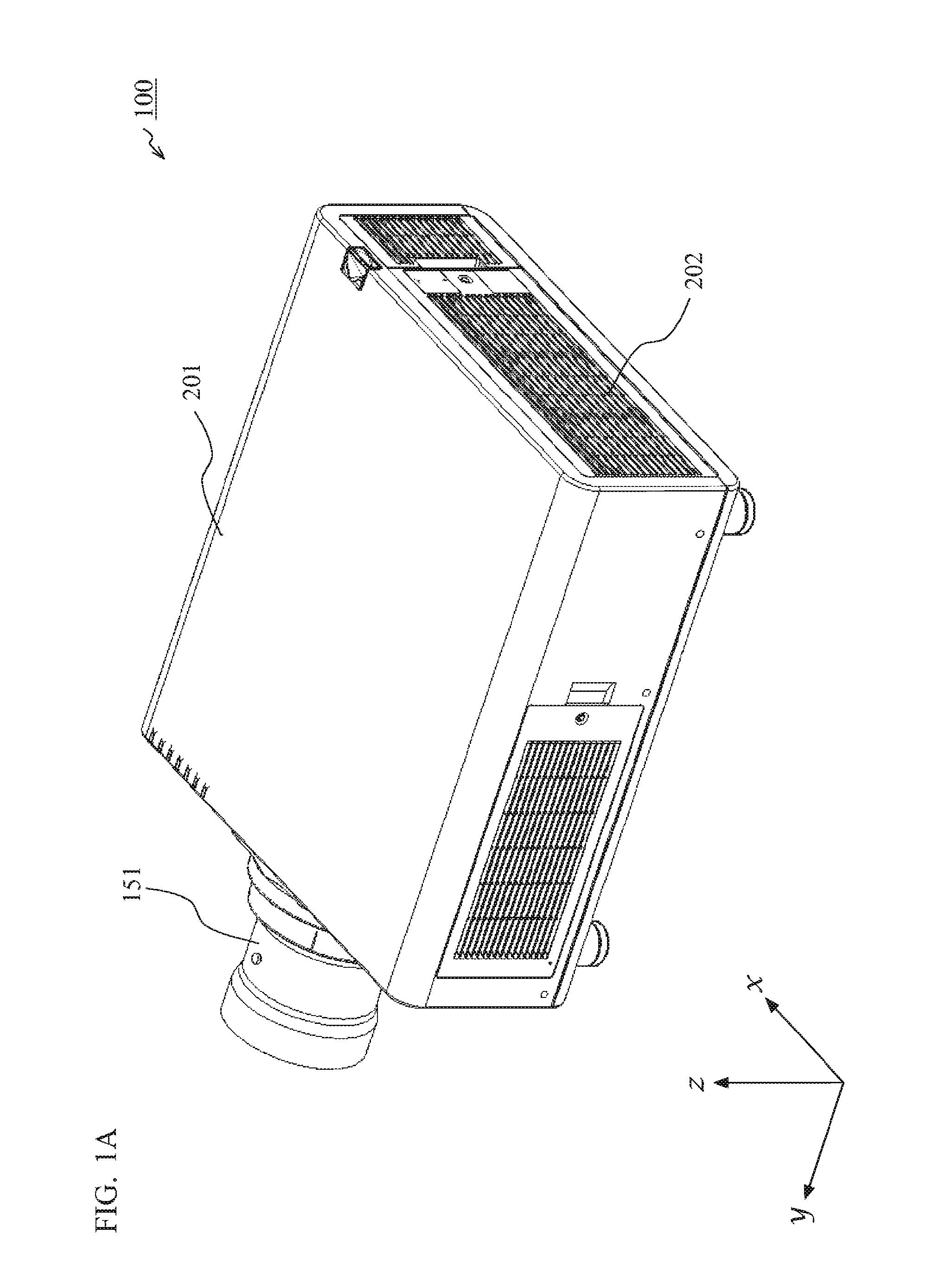
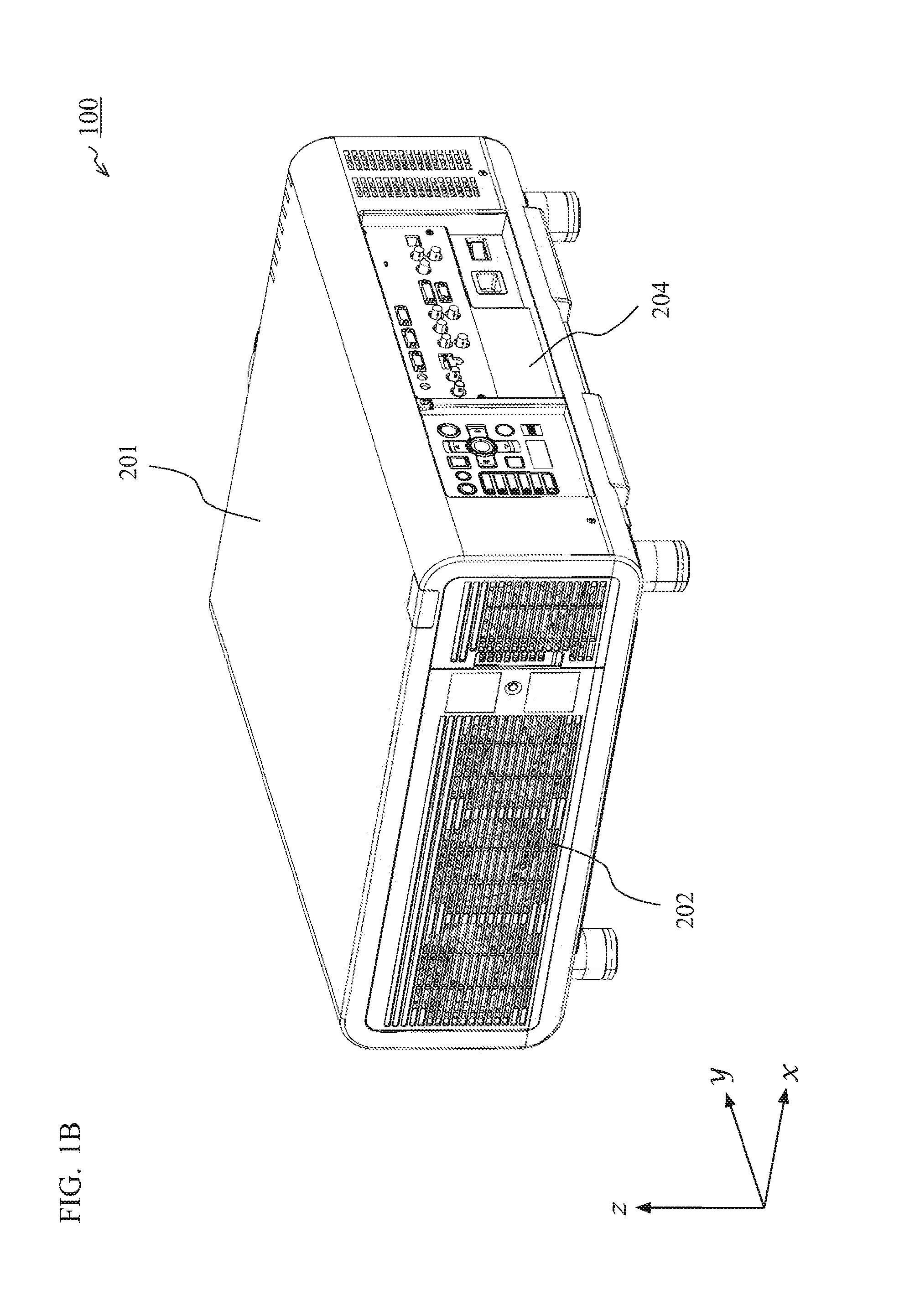
In such a usage mode, some of the projection type image display apparatuses will have cases whose top surfaces are blocked, leading to a problem of not being able to easily replace a light source.

Method used


Image

  • Projection type image display apparatus
  • Projection type image display apparatus
  • Projection type image display apparatus

Examples


Embodiment Construction

[0023]Hereinafter, embodiments will be described in detail with reference to the drawings as appropriate. However, there will be instances in which detailed description beyond what is necessary is omitted. For example, detailed description of subject matter that is previously well-known, as well as redundant description of components that are substantially the same will in some cases be omitted. This is to prevent the following description from being unnecessarily lengthy, in order to facilitate understanding by a person of ordinary skill in the art.

[0024]The inventors provide the following description and the accompanying drawings in order to allow a person of ordinary skill in the art to sufficiently understand the present disclosure, and the description and the drawings are not intended to restrict the subject matter of the scope of the patent claims.

[0025]The present disclosure is a technology applicable to a projection type image display apparatus including multiple light sourc...


PUM


Abstract

An opening cover of a case is removed. A light source module is held, and the light source module is pulled outside an opening of the case while guide groove parts and guide-rail parts slide along each other approximately parallelly to a case base. At this moment, junction cable connection terminals of the light source module become separated from power-supply connection terminals of a composite optical system. Replacement of a light source is conducted by replacing the light source module as a unit, or by replacing a light source section or a light source section each as a unit.

Description

BACKGROUND OF THE INVENTION[0001]1. Field of the Invention[0002]The present disclosure relates to a projection type image display apparatus including multiple light sources, and, more specifically, relates to a structure for removing a light source from a projection type image display apparatus to replace the light source.[0003]2. Description of the Background Art[0004]Generally, in a projection type image display apparatus referred to as a projector, a discharge lamp such as a high pressure mercury vapor lamp is used as a light source. With this discharge lamp, high brightness can be obtained with a small luminous body; however, since a plasma state is generated therein through inter-electrode electric discharges, the discharge lamp becomes close to as hot as 1000° C. and pressure therein becomes close to as high as 200 atm. Therefore, a lifespan of the discharge lamp representing the number of hours before its brightness is reduced to half is as short as 1500 to 3000 hours.[0005]S...

Claims


Application Information

Patent Timeline
Patent Type & Authority Applications(United States)
IPC IPC(8): G03B21/20
CPCG03B21/2013H04N9/315H04N9/3141G03B21/145
Inventor SARUWATARI, NAOTONOMOTO, MAMORUSAKAGUCHI, HIROKAZUOKUDA, MASAKAZU
Owner PANASONIC INTELLECTUAL PROPERTY MANAGEMENT CO LTD
Learn More