Robot arm control apparatus, robot arm control method, robot, robot arm control program, and integrated electronic circuit

a robot arm and control device technology, applied in the direction of manipulators, programmers, instruments, etc., can solve the problems of unsatisfactory operability, difficult to move in other directions, unsatisfactory operability, etc., to achieve high operability, improve safety, and eliminate the influence of the inertia of the robot arm body on the grip part during manipulation

Active Publication Date: 2013-07-18
PANASONIC CORP
View PDF11 Cites 27 Cited by
  • Summary
  • Abstract
  • Description
  • Claims
  • Application Information

AI Technical Summary

Benefits of technology

[0018]Accordingly, the inventors of the present disclosure have devised the structure of a robot arm in which the grip part gripped by the user when the robot arm is manipulated is mechanistically separated from the robot arm body. With this structure, by exerting tracking control of the robot arm such that the relative position of the robot arm body and the grip part falls within a prescribed threshold value range, the influence of inertia of the robot arm body can be eliminated when the user manipulates the grip part. Hence, a great improvement in operability can be achieved.
[0020]One non-limiting and exemplary embodiment provides a robot arm control device, a robot arm control method, a robot, a robot arm control program, and an integrated electronic circuit, with which the operability of a robot arm in performing work such as cooperative conveyance or direct manipulation can be improved, and with which a robot arm can be moved at ease highly safely.
[0033]With the robot arm control apparatus, the robot arm control method, the robot, the robot arm control program, and the integrated electronic circuit of the present disclosure, the end effector attached to the robot arm body and the grip part gripped by the user are mechanistically separated from each other, and the user can manipulate the robot arm by manipulating the grip part. As a result, the influence of the inertia of the robot arm body to the grip part during manipulation can be eliminated, and operability can highly be improved. Further, in the case where the grip part mechanistically separated from the robot arm is brought into contact with any other object, safety can be improved by changing the method of tracking control.

Problems solved by technology

Hence, the operability is still unsatisfactory.
In Patent Literature 2, since the motion of the retaining member is limited only in the horizontal direction, it is difficult to move in other directions.
Therefore, the operability is still unsatisfactory.
In Patent Literature 3, though the robot produces an assist force, the error of the estimated values causes the user to sense the weight of the target object or the robot, which leaves the operability unsatisfactory.
Further, since it is necessary to use a force sensor, a great cost will be incurred.

Method used


Image

  • Robot arm control apparatus, robot arm control method, robot, robot arm control program, and integrated electronic circuit
  • Robot arm control apparatus, robot arm control method, robot, robot arm control program, and integrated electronic circuit
  • Robot arm control apparatus, robot arm control method, robot, robot arm control program, and integrated electronic circuit

Examples


first embodiment

[0205]In the following, a description will be given of a robot according to a first embodiment of the present disclosure.

[0206]With the robot according to the first embodiment of the present disclosure, in order to improve the operability of the robot arm, a grip part gripped by the user when being manipulated is mechanistically separated from a robot arm body, and the robot arm body follows the shifting of the grip part (a detailed description thereof will be given later). However, exerting the tracking control in this manner invites an issue that, when the user is not gripping the grip part, the grip part falls and the robot arm falls down (a detailed description thereof will be given later). The first embodiment is directed to resolve the issue.

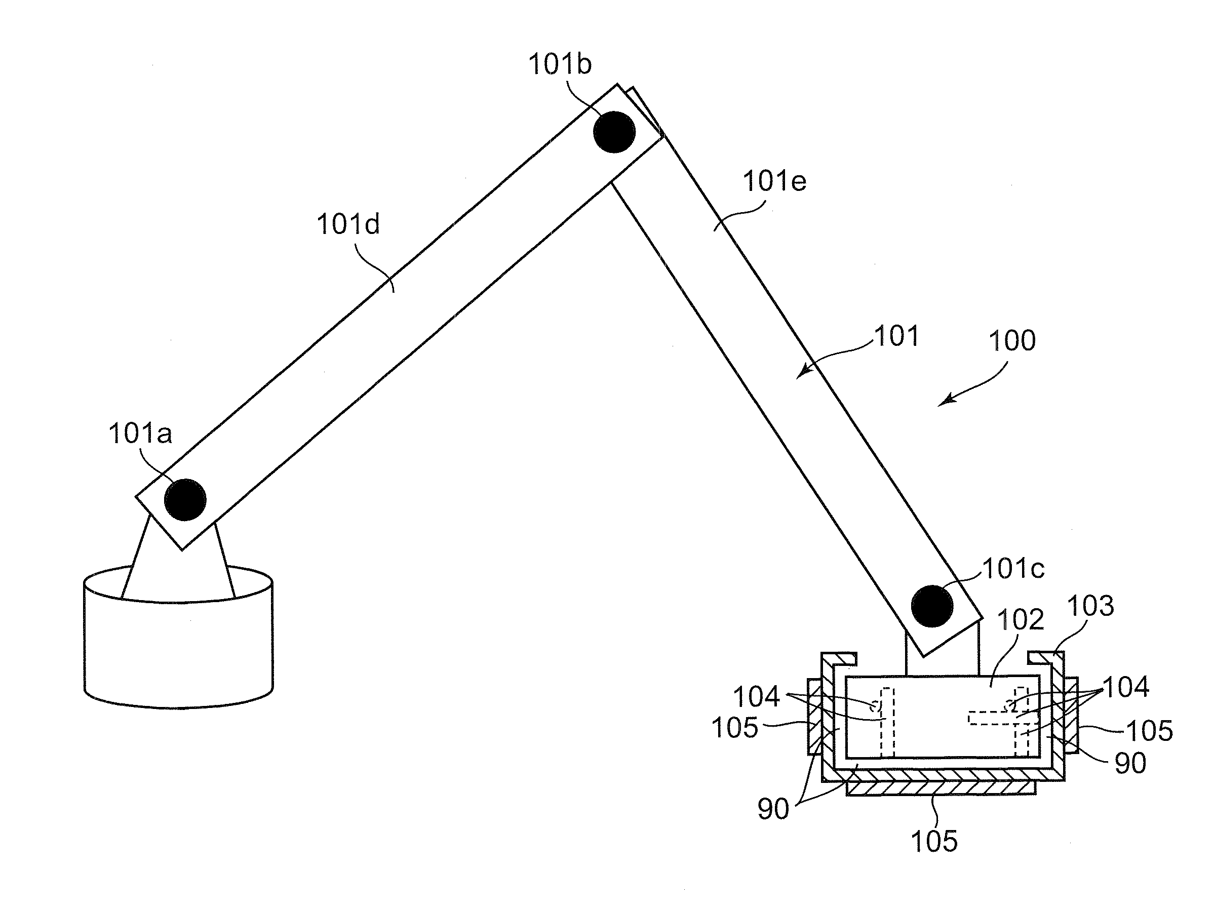
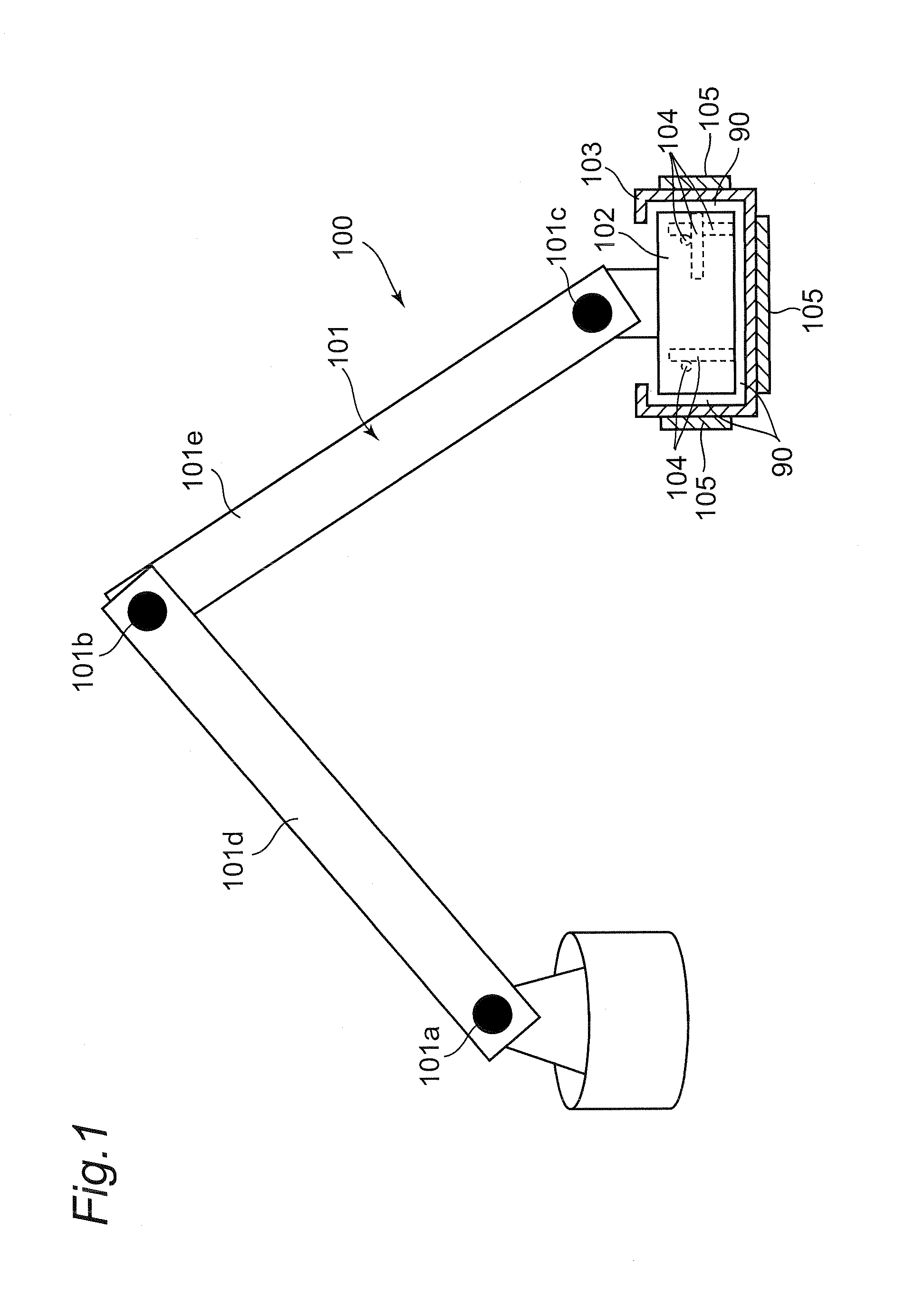
[0207]FIG. 1 shows a robot 601 including a robot arm 100 according to the first embodiment of the present disclosure. The robot arm 100 includes a manipulator 101 as an example of a body of the robot arm 100, an end effector 102, a grip pa...

second embodiment

[0282]In the following, a description will be given of a robot according to a second embodiment of the present disclosure.

[0283]In the first embodiment, the control unit 605 exerts tracking control of the manipulator 101 only when the user is gripping the grip part 103, to thereby resolve the issue that the manipulator 101 keeps falling down when the user is not gripping the grip part 103. Thus, safety is enhanced.

[0284]However, when the user starts gripping the grip part 103, if the value of relative position Δr of the grip part 103 to the end effector 102 is not 0, it is possible that the manipulator 101 sharply shifts and becomes dangerous immediately after the user grips the grip part 103. That is, in the case where the relative position Δr is not 0 when tracking control is started, irrespective of the magnitude of the relative position Δr, tracking control is abruptly performed immediately after the tracking control is started, and it is highly possible to become dangerous. On ...

third embodiment

[0313]In the following, a description will be given of a robot according to a third embodiment of the present disclosure.

[0314]In the second embodiment, by the control device 602 causing the manipulator 101 to perform tracking control slowly during a certain time from when the user starts gripping the grip part 103, safety at the start of tracking control is improved.

[0315]However, when the tracking control ends, the grip part 103 may fall and hit the end effector 102 hardly.

[0316]This state will be described using FIGS. 21A to 21C. FIGS. 21A to 21C show the procedure of the manipulator 101 performing the tracking when the user and the manipulator 101 cooperatively convey the target object 1101. The state transits in an order of FIG. 21A→FIG. 21B→FIG. 21C.

[0317]Firstly, FIG. 21A shows the state where the user's hand 801 is gripping the grip part 103 and the manipulator 101 is performing tracking control.

[0318]Next, FIG. 21B shows the state of the moment when the user's hand 801 rele...


PUM


Abstract

A robot arm includes a grip part which is structured to be separated from an end effector attached to the robot arm. When the grip part is gripped by the user and shifted, the robot arm shifts tracking the grip part. Further, the grip part includes contact sensors, and a tracking control method is switched according to the value of the contact sensors.

Description

CROSS-REFERENCE TO RELATED APPLICATIONS[0001]This is a continuation application of International Application No. PCT / JP2012 / 000035, with an international filing date of Jan. 5, 2012, which claims priority of Japanese Patent Application No.: 2011-015228 filed on Jan. 27, 2011, the content of which is incorporated herein by reference.TECHNICAL FIELD[0002]The technical field relates to a robot arm control device, a robot arm control method, a robot having the robot arm control device, a robot arm control program, and an integrated electronic circuit, for generating operations of a robot to teach or carry out desired work such as cooperative conveyance.BACKGROUND ART[0003]In recent years, model changes frequently take place for producing various types in small lots at manufacturing sites. In order to automate screw tightening work, fitting work or attaching work of components, inserting work of flexible substrates or the like, or polishing work by robots at recent manufacturing sites wh...

Claims


Application Information

Patent Timeline
Patent Type & Authority Applications(United States)
IPC IPC(8): B25J13/02
CPCB25J13/02B25J13/081G05B19/423G05B2219/36453Y10S901/33Y10S901/02Y10S901/20Y10S901/46Y10S901/09Y10S901/04Y10S901/03Y10S901/30
Inventor FUDABA, YUDAIYAMAMOTO, MASAKITSUSAKA, YUKOSATO, TAICHI
Owner PANASONIC CORP
Why Eureka
Try Eureka