Al technical title is built by PatSnap Al team. It summarizes the technical point description of the patent document.
a valve device and tire technology, applied in the direction of tires, vehicle components, rims, etc., can solve the problems of loss of control over the car, extreme danger to the driver, and lack of suitable provision of typical valve devices
Inactive Publication Date: 2013-07-25
BAO LEY
View PDF11 Cites 14 Cited by
Summary
Abstract
Description
Claims
Application Information
AI Technical Summary
This helps you quickly interpret patents by identifying the three key elements:
Problems solved by technology
Method used
Benefits of technology
[0014]The tube includes at least one guide slot or rib extended in the compartment thereof, and the valve piece includes at least one guide member for engaging with the guide slot or rib of the tube and for g
Problems solved by technology
The valve bodies of the typical valve devices lack a suitable provision for sealing the valve body to avoid loss of air, and a separate gasket or sealing member is further required to be mounted or engaged between the wheel rim and the valve stem for making an air tight seal between the valve stems or devices and the wheel rim.
However, a suitable air tight seal for the valve devices is important for the driver of the cycle vehicles, and the loss of t
Method used
Image
Click on the blue label to locate the original text in one second.
Reading with bidirectional positioning of images and text.
Examples
Embodiment Construction
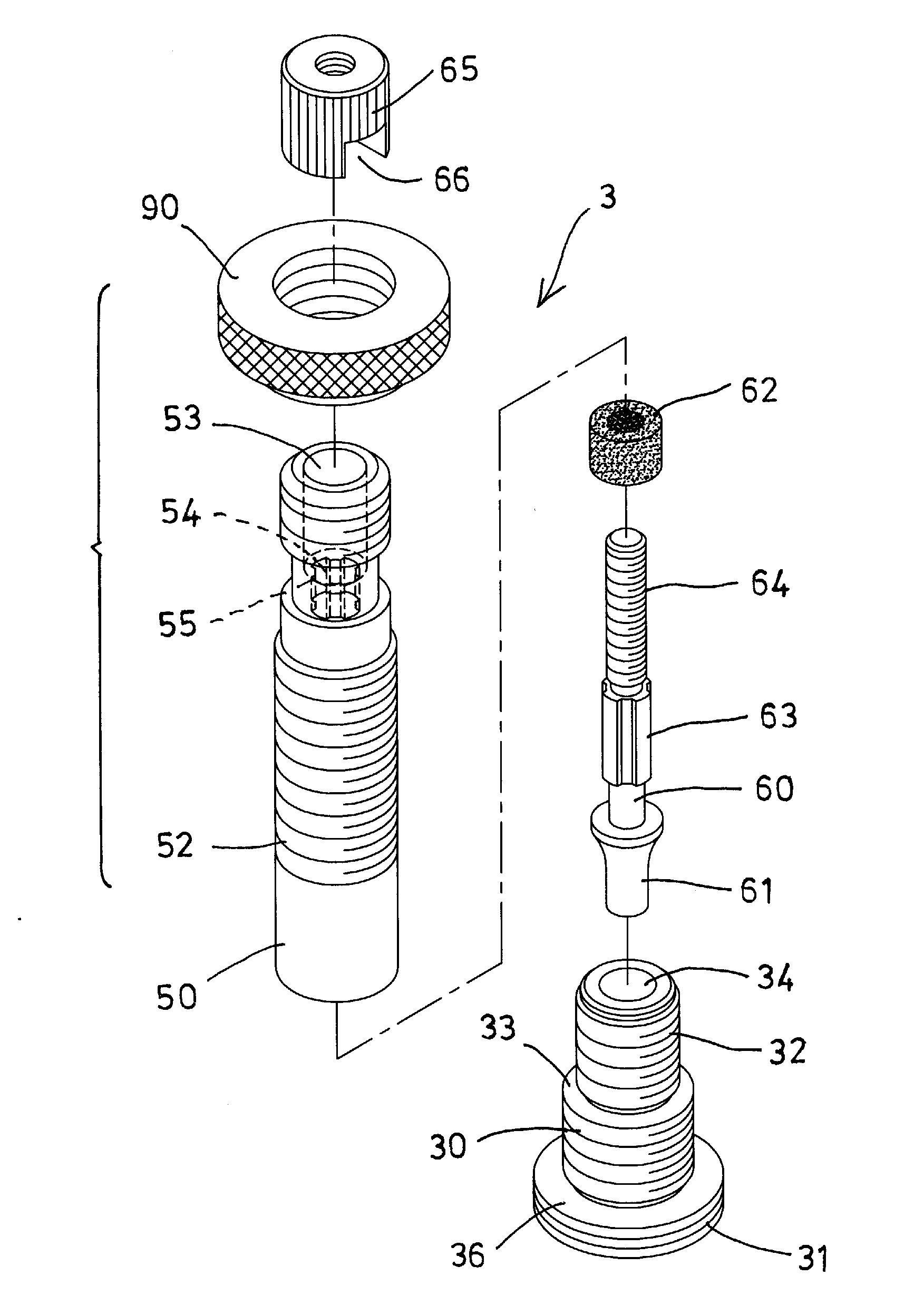
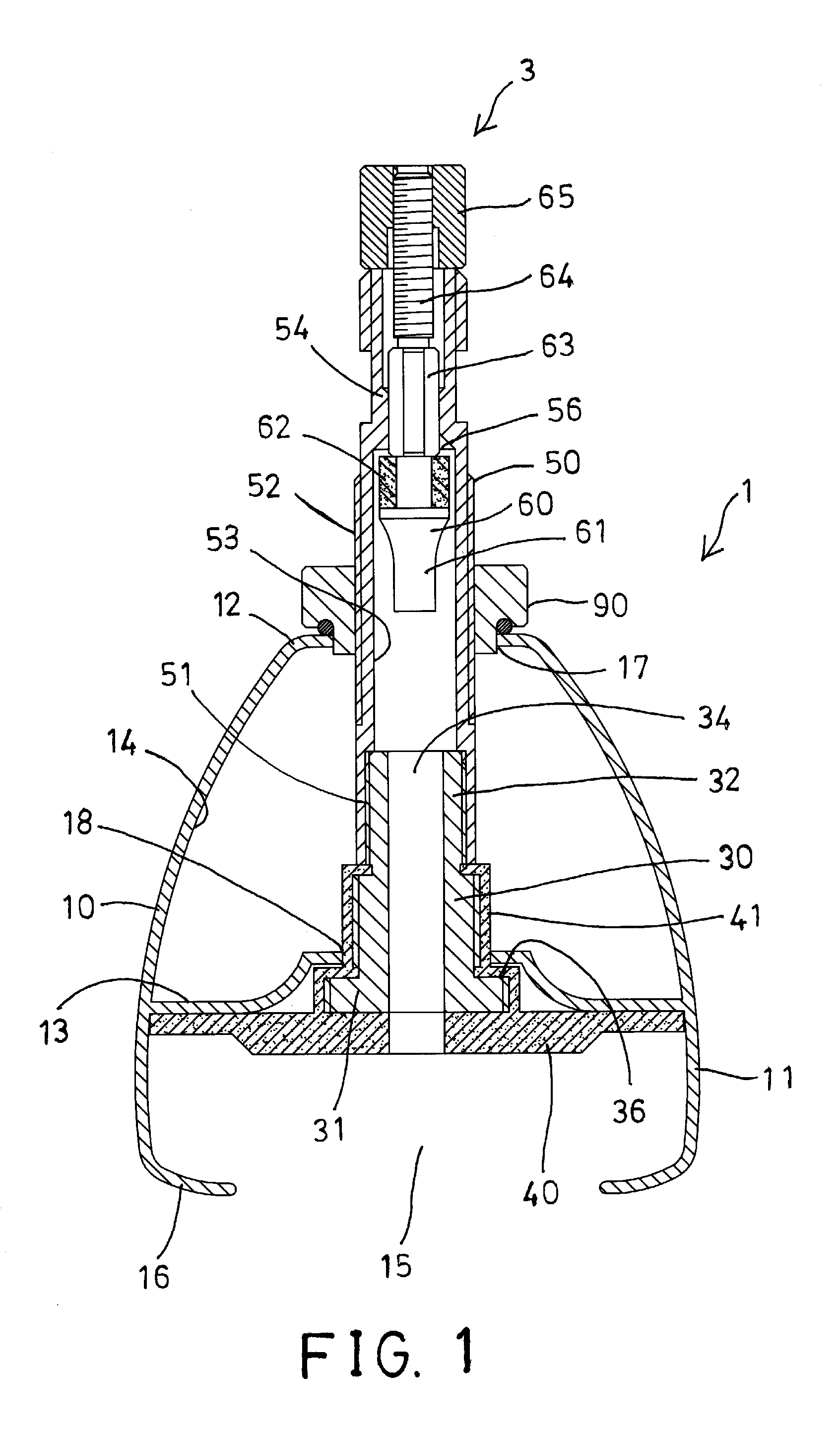
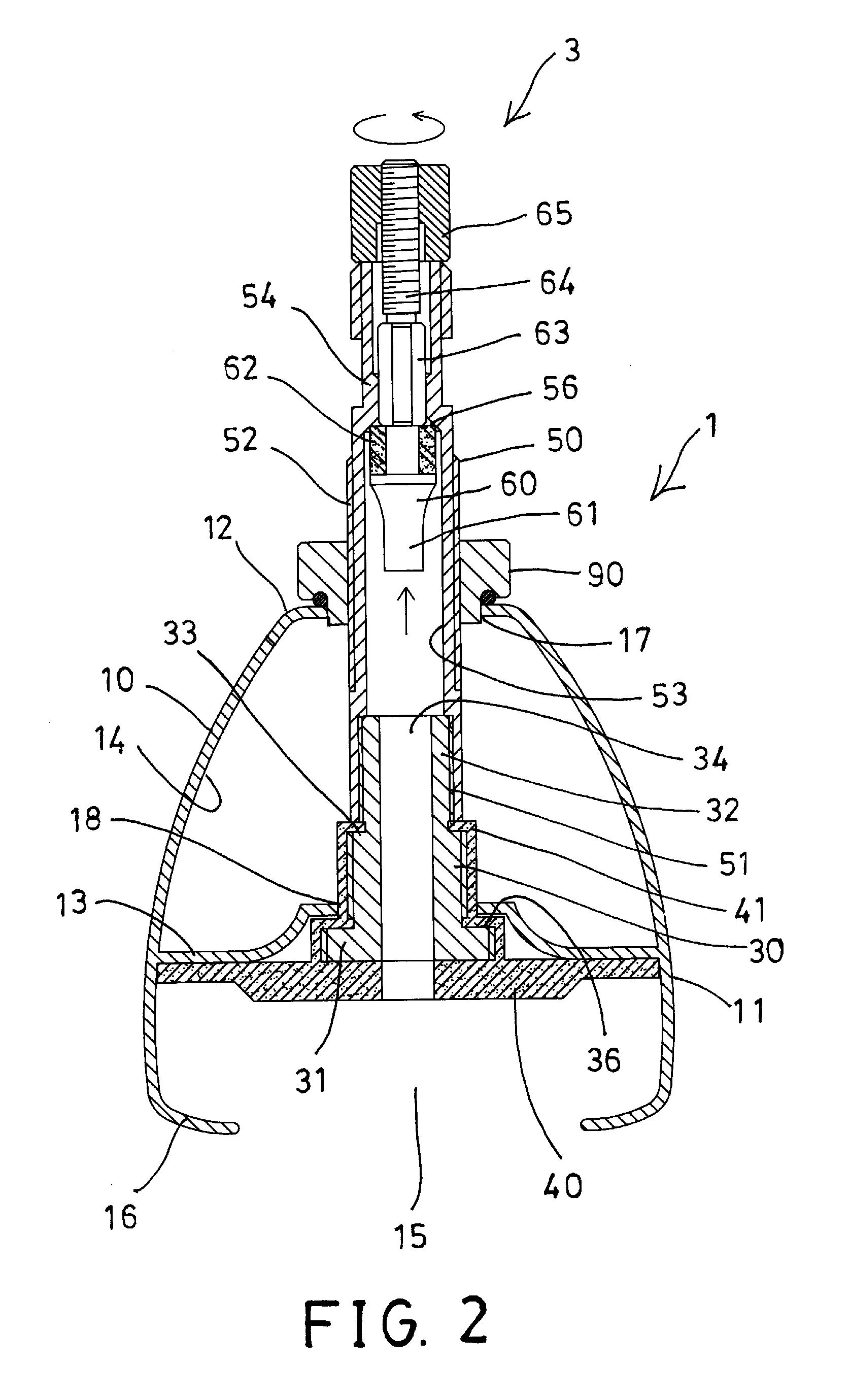
[0025]Referring to the drawings, and initially to FIGS. 12, a wheel rim assembly 1 in accordance with the present invention comprises a rim member 10 including a profiled structure having a substantially A-shaped section, with two side walls 11 which converge and are joined together to form a base 12, and a bridge 13 extending between the two side walls 11 for forming or defining an inner chamber 14 by the bridge 13 and the base 12. The rim member 10 further includes an outer peripheral channel 15 formed or defined by the bridge 13 and the tire-holding fins 16 that are formed or extended from the radially outer portions of the side walls 11, for coupling to a tire (not shown), particularly a tubeless tire.
[0026]It should be noted that the base 12 is not only defined as the inner peripheral joining zone between the two side walls 11 (which in turn can be relatively narrow as in the illustrated example or narrower or wider), but more generally the portion of the side walls 11 below th...
PUM
Abstract
A wheel rim device includes a rim member having a bridge extending between two side walls, and a valve device having a valve stem engaged with the bridge and having a sealing member attached to the valve stem for engaging with the bridge and for anchoring the valve stem to the bridge of the rim member and for making an air tight seal between the valve stem and the rim member, and the sealing member includes a casing engaged onto the valve stem and engaged between the valve stem and the bridge for further making a solid and stable air tight seal between the valve stem and the rim member. The casing is engaged onto a flanged head of the valve stem for engaging with the bridge.
Description
BACKGROUND OF THE INVENTION[0001]1. Field of the Invention[0002]The present invention relates to a valve device for a tubeless tire, and more particularly to a valve device for tubeless tires, particularly those used in show cars, bicycles, motor cycles, tricycles, unicycles, or the like, although the invention need not be limited thereto.[0003]2. Description of the Prior Art[0004]Typical valve devices for bicycles, motor cycles, unicycles, tricycles, show cars, or the like require custom installation of the valve stem into a wheel rim, and comprise a valve stem to be attached or mounted or secured or engaged into the drilled hole of the wheel rim, and a gasket or sealing member required to be mounted or engaged between the wheel rim and the valve stem for making an air tight seal between the valve stems or devices and the wheel rim.[0005]For example, U.S. Pat. No. 4,760,860 to Madrona, U.S. Pat. No. 4,819,685 to Pagani, and U.S. Pat. No. 5,211,782 to Thelen disclose several of the ...
Claims
Application Information
Patent Timeline
Application Date:The date an application was filed.
Publication Date:The date a patent or application was officially published.
First Publication Date:The earliest publication date of a patent with the same application number.
Issue Date:Publication date of the patent grant document.
PCT Entry Date:The Entry date of PCT National Phase.
Estimated Expiry Date:The statutory expiry date of a patent right according to the Patent Law, and it is the longest term of protection that the patent right can achieve without the termination of the patent right due to other reasons(Term extension factor has been taken into account ).
Invalid Date:Actual expiry date is based on effective date or publication date of legal transaction data of invalid patent.