Heat medium heating device

Inactive Publication Date: 2013-07-25
MITSUBISHI HEAVY IND LTD
View PDF4 Cites 6 Cited by
  • Summary
  • Abstract
  • Description
  • Claims
  • Application Information

AI Technical Summary

Benefits of technology

[0017]According to the heat medium heating device of the present invention, after the PTC heater is arranged between the inner case and the outer case, pipe enlargement is performed on the inner case, thereby exerting a pressure between the inner case and the PTC heater and between the PTC heater and the outer case. Therefore, the heat medium heating device

Problems solved by technology

This is because, if adherence of the electrode plate to the PTC element is degraded, he

Method used


Image

  • Heat medium heating device
  • Heat medium heating device
  • Heat medium heating device

Examples


Example

First Embodiment

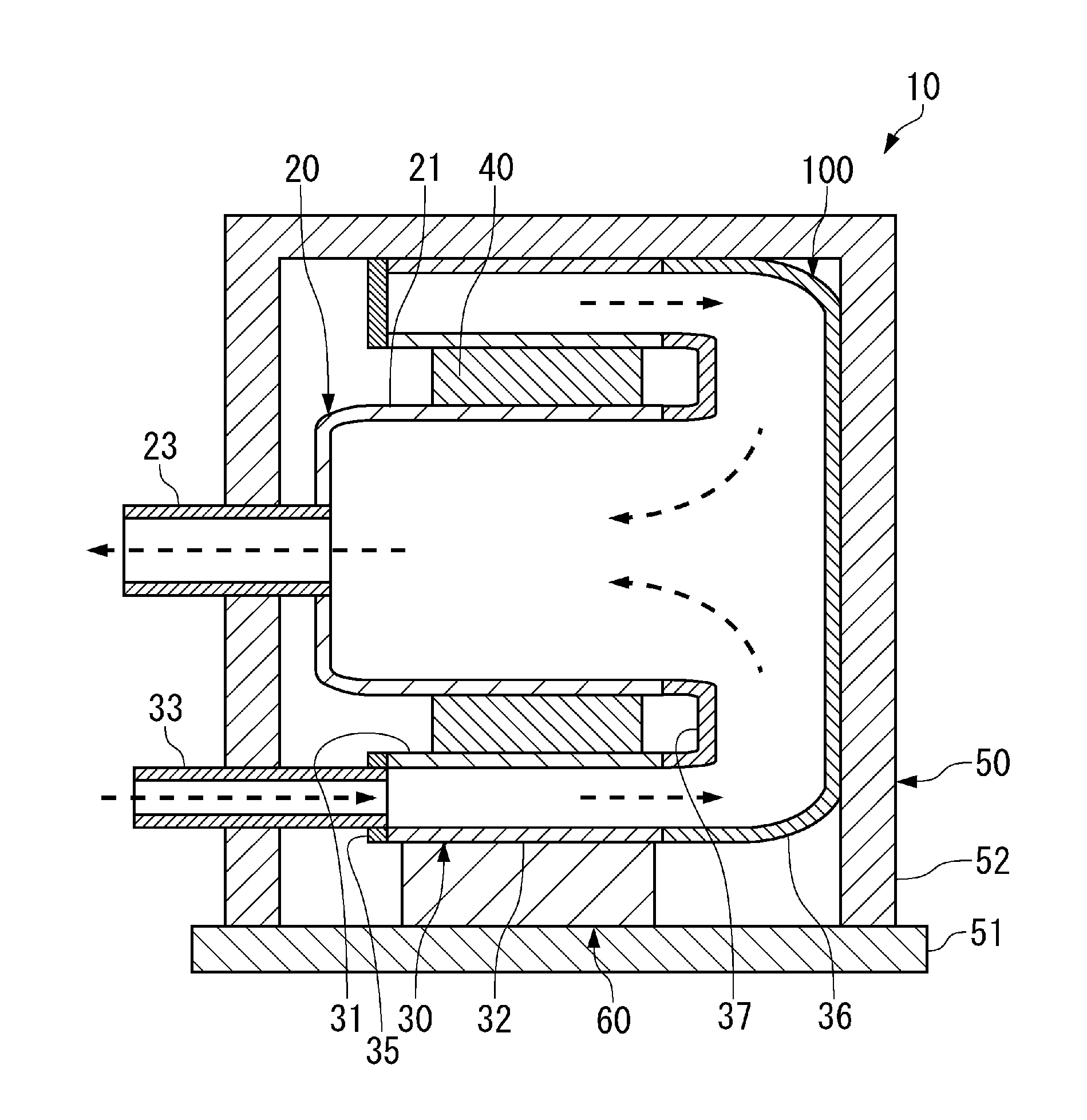
[0026]A heat medium heating device 10 according to a first embodiment is used in, for example, an air conditioning device for vehicle 1, which will be described further below. In this case, a heat medium heated by the heat medium heating device 10 is supplied to a radiator 6, and serves as a heat source for warming air.

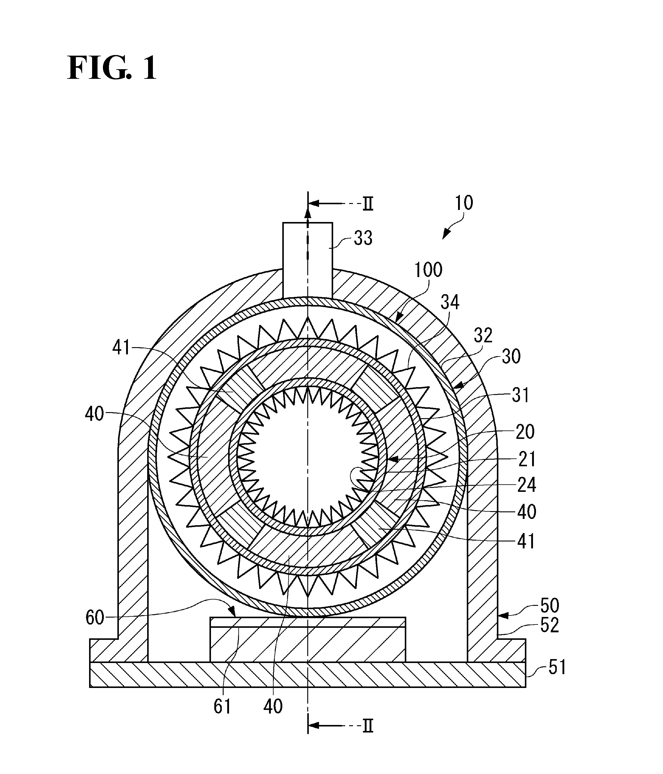
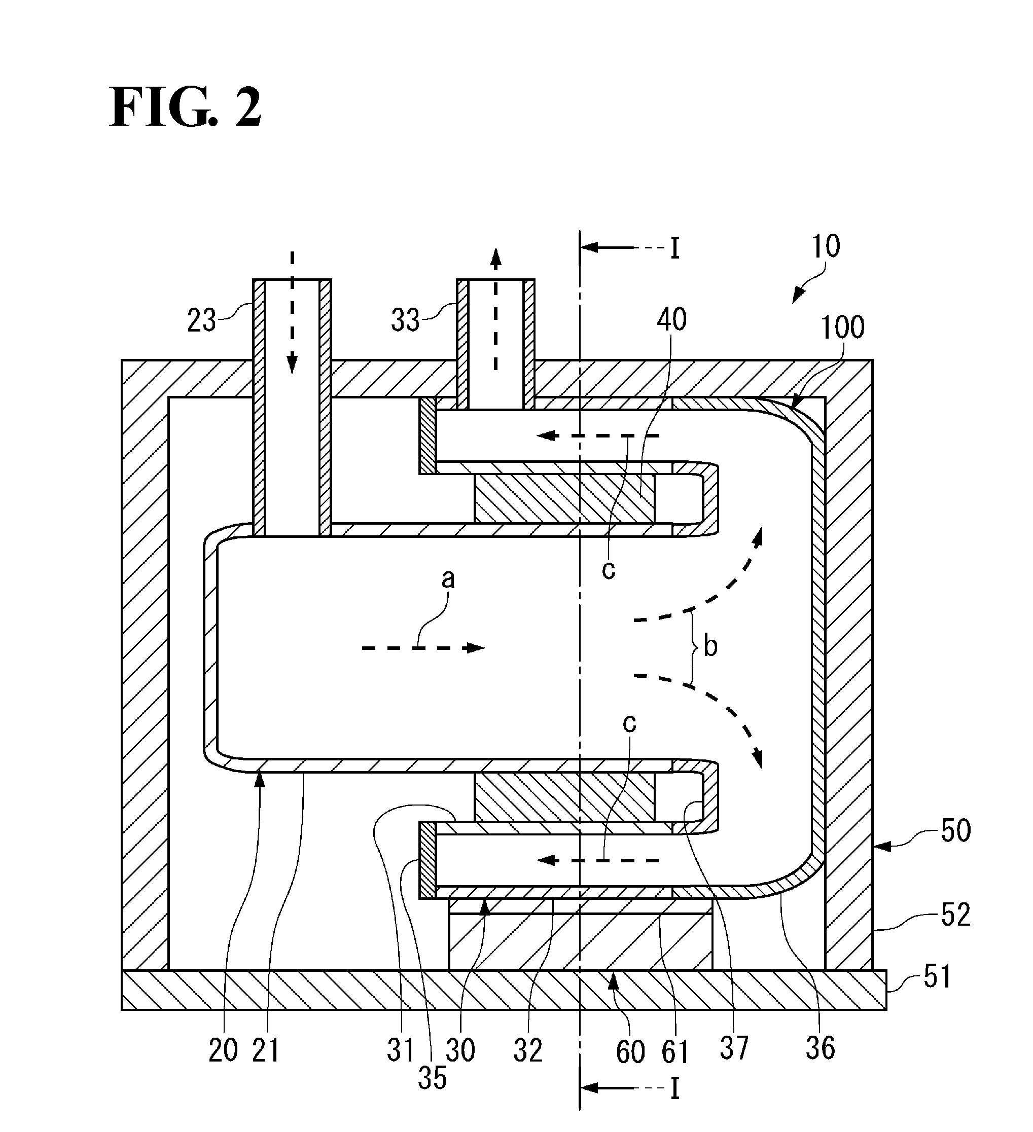
[0027]The heat medium heating device 10 includes, as shown in FIG. 1 and FIG. 2, an inner case unit 20 and an outer case unit 30 arranged around the inner case unit 20. Between the inner case unit 20 and the outer case unit 30, PTC heaters 40 are interposed and held to configure a heater unit 100 together with the inner case unit 20 and the outer case unit 30. A heat medium to be introduced into the heat medium heating device 10 sequentially flows through the inner case unit 20 and then the outer case unit 30 while being heated by the PTC heaters 40, and the heat medium is then discharged from the heat medium heating device 10.

20>

[0028]The inner case u...

Example

[0050]Next, a second embodiment of the present invention is described with reference to FIG. 5 and FIG. 6.

[0051]A heater unit 200 according to the second embodiment is different from the heater unit 100 according to the first embodiment in that the heat medium flows exclusively in the circumferential direction. In the following, this different point is mainly described.

[0052]The heater unit 200 includes an inner case unit 220 and an outer case unit 230 arranged around the inner case unit 220. The PTC heaters 40 are held as being interposed Between the inner case unit 220 and the outer case unit 230.

220 and Outer Case Unit 230>

[0053]To the inner case unit 220, a cylindrical inner case main body 221 having both ends in an axial direction open, an inner wall tube 222 arranged inside the inner case main body 221 so as to be surrounded by the inner case main body 221, and an introduction tube 223 and a discharge tube 224 connected to the inner wall tube 222 are connected. The introductio...


PUM


Abstract

A heat medium heating device 10 includes an inner case main body 21 having a flow path of a heat medium formed inside, an outer case main body 31 arranged on an outer peripheral side of the inner case main body 21 and having a flow path of the heat medium formed outside, and a PTC heater 40 held as being interposed between the inner case main body 21 and the outer case main body 31. The inner case main body 21 and the outer case main body 31 each may have a circular outer shape or a rectangular outer shape. Also, the inner case main body 21 and the outer case main body 31 are preferably provided with fins 24 and 34, respectively, facing the flow path of the heat medium.

Description

TECHNICAL FIELD[0001]The present invention relates to a device that heats a heat medium by using a PTC (Positive Temperature Coefficient) heater.BACKGROUND ART[0002]A heat medium heating device that heats a medium to be heated has been conventionally known, which uses a PTC heater having a positive character thermister element (PTC element) as a heating element.[0003]The PTC heater has a characteristic such that current consumption is decreased when the temperature of the heater increases and is then stabilized at a low value when the temperature reaches a certain temperature in a saturated region. By using this characteristic, power consumption can be saved. Also, an abnormal increase in temperature of a heating part can be advantageously prevented. With these features, the PTC heater is used in many fields of technology. For example, as indicated in Patent Document 1, it is known that the PTC heater is used as an auxiliary heater for heating an automobile.[0004]The PTC heater gene...

Claims


Application Information

Patent Timeline
IPC IPC(8): H05B3/02H05B3/06
CPCB60H1/2221H01C7/02H05B3/50H05B3/026H05B3/06H05B2203/02H05B3/0014
Inventor WATANABE, YASUNORICHUMAN, YASUHARUKUGA, KAZUNORIKOMINAMI, SATOSI
Owner MITSUBISHI HEAVY IND LTD
Why Eureka
Try Eureka