Vehicle power supply system

a power supply system and vehicle technology, applied in the direction of power to the power outlet, battery/fuel cell control arrangement, electric devices, etc., can solve the problems of increasing the cost per unit length of the connection cable, inconvenient for users, and large force required to bend the connection cable, so as to improve the stiffness and prevent the infiltration of the vehicle interior

Active Publication Date: 2013-07-25
HONDA MOTOR CO LTD
View PDF2 Cites 14 Cited by
  • Summary
  • Abstract
  • Description
  • Claims
  • Application Information

AI Technical Summary

Benefits of technology

[0027]In the case of the above (7), the contactor is disposed at a portion right above the side frame extending in the forward and rearward direction of the vehicle body among the vehicle body frames (at a position which overlaps with the side frame in the upward and downward direction of the vehicle body). Therefore, the support portion of the contactor may securely have enhanced stiffness by the side frame, and the contactor may be securely protected.
[0028]In the case of the above (8), due to the fuel cell vehicle which drives by the fuel cell using the hydrogen gas as a fuel, the hydrogen tank side handling the hydrogen gas and the contactor side may be securely partitioned, and thus the hydrogen gas may be securely prevented from infiltrating into the vehicle interior side.

Problems solved by technology

For this reason, a location, which is able to supply the electric power from the storage battery of the vehicle to the outside, is restricted to the vicinity of an installation location of the stationary fuel cell system, thereby being inconvenient for a user.
In addition, Japanese Unexamined Patent Application, First Publication No. 2006-325392 does not disclose a specific vehicle configuration, and thus there is still a need to think about practical use.
In particular, in a case of adopting the connection cable having a large diameter for high-voltage and large-current so as to correspond to high-voltage and large-current, a large force is additionally required to bend the connection cable and the cost per unit length of the connection cable increases.

Method used


Image

  • Vehicle power supply system
  • Vehicle power supply system
  • Vehicle power supply system

Examples


first embodiment

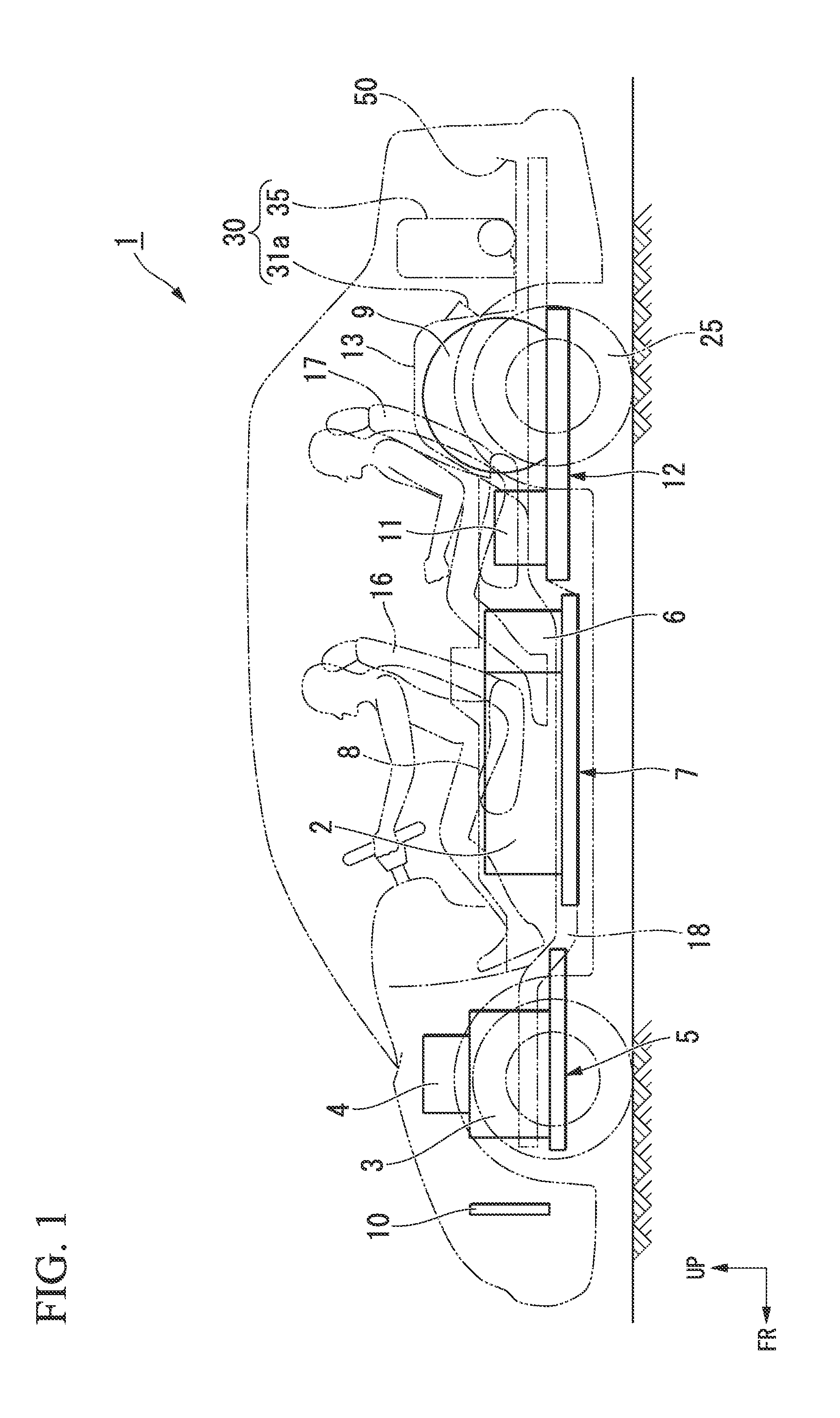
[0042]Hereinafter, a fuel cell automobile (an electrically driven vehicle, a fuel cell vehicle) according to a first embodiment of the present invention will be described with reference to the accompanying drawings. In the following description, directions such as “forward, rearward, left, and right directions” are the same as the directions in the vehicle unless indicated otherwise. Also, a central arrow FR, an arrow LH, and an arrow UP respectively refer to the forward direction, the left direction, and the upward direction of the vehicle, in the drawings.

[0043]FIG. 1 is a side view illustrating a fuel cell automobile 1 (an electrically driven vehicle, a fuel cell vehicle) according to the embodiment. In FIG. 1, reference numerals 16 and 17 are a front seat and a rear seat in a vehicle interior, respectively.

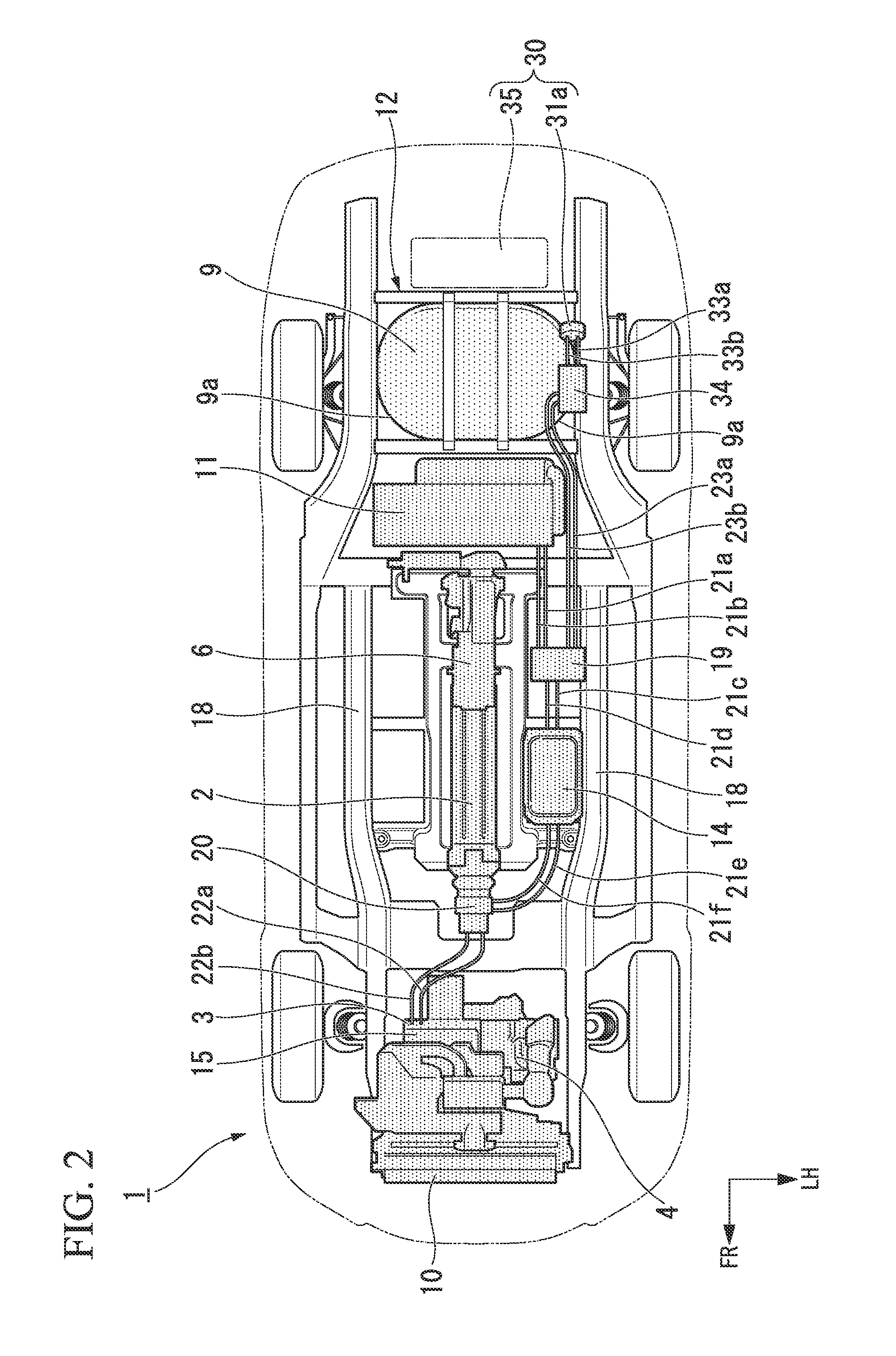
[0044]FIG. 2 is a top view illustrating the fuel cell automobile 1.

[0045]As shown in FIG. 1, the fuel cell automobile 1 is to mount a fuel cell stack 2 (hereinafter, referred ...

second embodiment

[0100]Hereinafter, an electrically driven vehicle according to a second embodiment of the present invention will be described with reference to the accompanying drawings. In the following description, directions such as “forward, rearward, left, and right directions” are the same as the directions in the vehicle unless indicated otherwise. Also, a central arrow FR, an arrow LH, and an arrow UP respectively refer to the forward direction, left direction, and upward direction of the vehicle, in the drawings.

[0101]The electrically driven vehicle according to the embodiment is a fuel cell automobile (a fuel cell vehicle) 101 using a fuel cell 102 as a main power source for driving the vehicle.

[0102]FIGS. 8 and 9 are a side view and a top view schematically illustrating a configuration of the fuel cell automobile 101. In more detail, FIG. 8 is a side view schematically illustrating the whole vehicle which shows a cross-section of an only rear portion of a vehicle body taken along portion...


PUM


Abstract

A vehicle power supply system includes a power supply connector having a power supply port which is provided within a trunk room and electrically connected to a DC power source, and an inverter device which is provided separately from a fuel cell automobile (an electrically driven vehicle) and is disposed within the trunk room, wherein the trunk room is provided therein with an inverter installation space where the inverter device may be installed at a position which does not overlap with the power supply port when viewed from a forward and rearward direction of the vehicle, and the invert device is provided with a connection cable which is drawn from a side surface thereof and of which a front end portion has a connector portion connected to the power supply port.

Description

CROSS-REFERENCE TO RELATED APPLICATION[0001]This application claims priority based on Japanese Patent Application No. 2012-012168, filed on Jan. 24, 2012, and Japanese Patent Application No. 2012-012169, filed on Jan. 24, 2012, the contents of which are incorporated herein by reference.BACKGROUND[0002]1. Field of the Invention[0003]The present invention relates to a vehicle power supply system which supplies electrical power from a DC (Direct Current) power source of an electrically driven vehicle to an external AC (Alternating Current) device.[0004]2. Description of Related Art[0005]In the past, a vehicle power supply system has been proposed which uses a DC power source such as a battery or a fuel cell mounted in an electrically driven vehicle such as an electric vehicle or a fuel cell automobile and supplies electric power to a home electric appliance (for example, see Japanese Unexamined Patent Application, First Publication No. 2006-325392).[0006]A power supply system (a vehicl...

Claims


Application Information

Patent Timeline
Patent Type & Authority Applications(United States)
IPC IPC(8): B60L1/00
CPCB60L11/1881Y02T90/34B60L1/006B60L2270/40B60L58/30Y02T90/40
Inventor MOURI, TAKANORIKUYAMA, KAZUHIKOEGUCHI, HIROYUKIOGAWA, MAKOTOAZUMA, KOICHIKANEGAE, TAKESHIGOTO, TAKESHINONAKA, HIROIJINBO, TAKUMI
Owner HONDA MOTOR CO LTD
Why Eureka
Try Eureka