Calibration targets for microscope imaging

a microscope and target technology, applied in the field of microscope imaging technologies, can solve the problems of not being able to obtain information about the nanoscale or microscale contents of volumes of samples below the surface, the time needed for super-resolution imaging is not favorable to imaging of live cells, and the exposure of living cells to deleterious or fatal levels of electromagnetic radiation

Active Publication Date: 2013-07-25
LEICA MICROSYSTEMS CMS GMBH
View PDF23 Cites 19 Cited by
  • Summary
  • Abstract
  • Description
  • Claims
  • Application Information

AI Technical Summary

Problems solved by technology

Scanning-tunneling and atomic-force microscopy are non-optical techniques for obtaining high-resolution images of the surfaces of materials, but cannot be used to obtain information about the nanoscale or microscale contents of volumes of samples below surfaces.
The time needed for super-resolution imaging does not favor imaging of live cells, which tend to move and change shape over the periods of time needed to collect the relatively weak signal from which super-resolution images are constructed.
The long time periods needed to collect the relatively weak signal may also result in exposure of living cells to deleterious or fatal levels of electromagnetic radiation, including ultraviolet light.
The time needed to acquire sufficient data for super-resolution imaging may also represent a significant experimental constraint, regardless of the type of sample that is imaged.

Method used


Image

  • Calibration targets for microscope imaging
  • Calibration targets for microscope imaging
  • Calibration targets for microscope imaging

Examples


Embodiment Construction

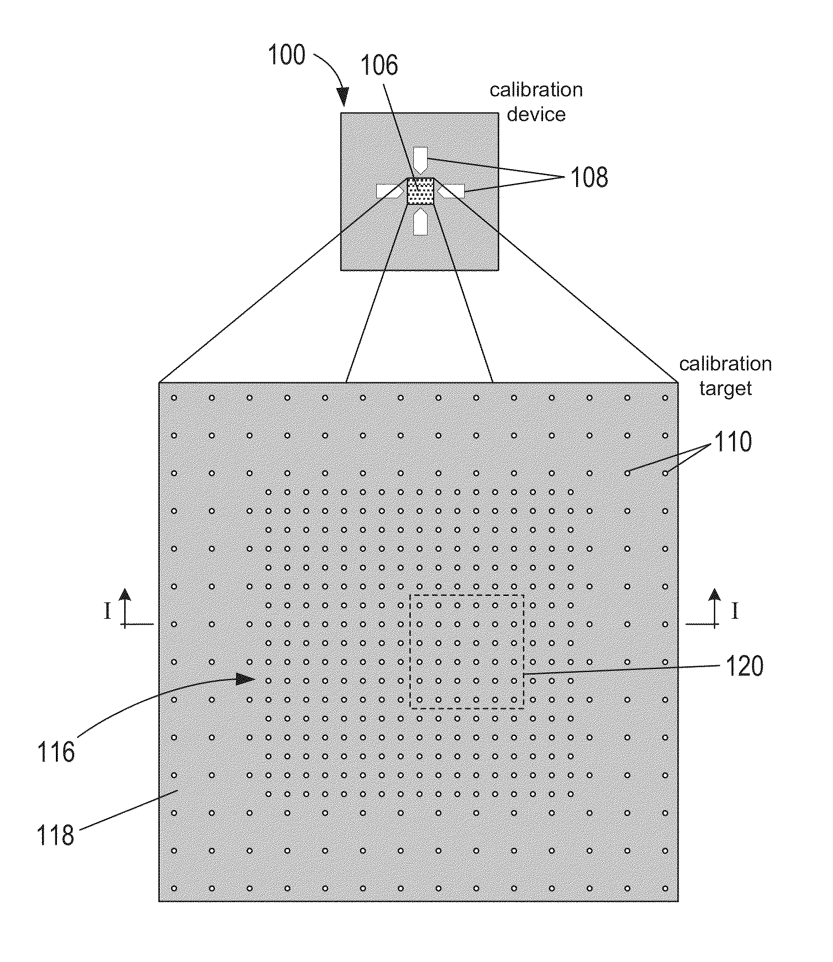
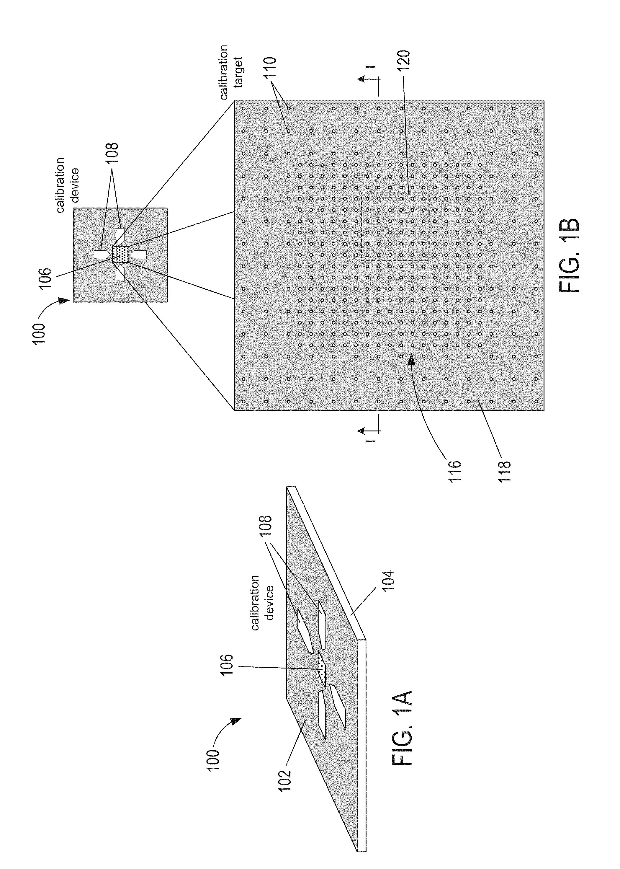
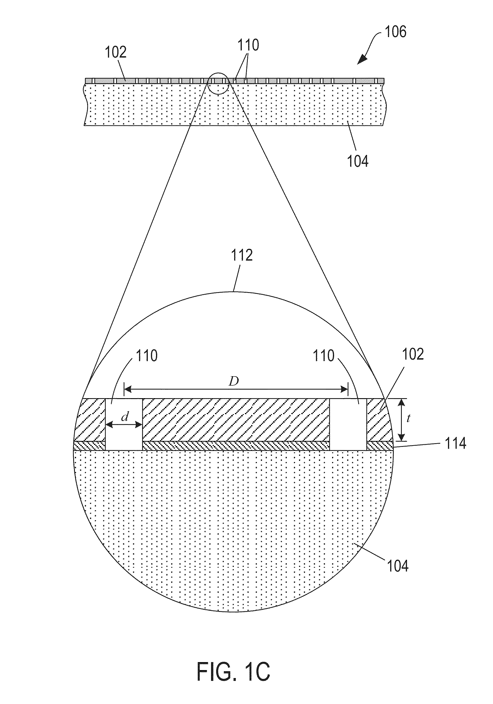
[0026]FIGS. 1A-1C show different views of an optical microscope calibration device 100. In FIG. 1A, the calibration device 100 includes an opaque layer 102 disposed on a transparent plate 104. The opaque layer 102 includes a calibration target 106 located in the approximate center of the device 100. The device 100 may also include a number of directional arrows 108 disposed on the opaque layer 102 outer surface to aid in positioning the device 100 so that the target 106 is located within the field of view of a microscope objective. FIG. 1B shows a magnified view of the calibration target 106 composed of a two-dimensional square-lattice of features 110. In other embodiments, the features 108 can have other two-dimensional lattice arrangements, such as rhombic, a hexagonal, a rectangular, parallelogrammic, or even a random distribution of features. The features 110 can be holes formed in the opaque layer 102. FIG. 1C shows a cross-sectional view of the calibration target 106 portion o...


PUM


Abstract

This disclosure is directed to optical microscope calibration devices that can be used with optical microscopes to adjust the microscope imaging parameters so that images of samples can be obtained below the diffraction limit. The microscope calibration devices include at least one calibration target. Each calibration target includes a number of features with dimensions below the diffraction limit of a microscope objective. Separate color component diffraction limited images of one of the calibration targets are obtained for a particular magnification. The color component images can be combined and image processed to obtain a focused and non-distorted image of the calibration target. The parameters used to obtain the focused and non-distorted image of the calibration target can be used to obtain focused and non-distorted images of a sample for the same magnification by using the same parameters.

Description

CROSS-REFERENCE TO RELATED APPLICATIONS[0001]This application claims priority to U.S. provisional patent application No. 61 / 387,737 filed Sep. 29, 2010; the disclosure of which is incorporated herein by reference in its entirety.TECHNICAL FIELD[0002]The disclosure relates to microscopy imaging technologies, and, in particular, to systems and methods for enhancing microscope magnification.BACKGROUND OF THE INVENTION[0003]Many different types of imaging systems are employed in modern scientific research to acquire images of small or distant objects, including extremely high-resolution electron microscopes, extremely high-resolution scanning tunneling (“STM”) and atomic-force (“AFM”) imaging instruments, and many different types of optical microscopes, telescopes, and image-generating sensors. As with most types of imaging devices, instruments, and techniques, there are many different trade-offs and balances associated with different types of microscopy. For example, transmission elect...

Claims


Application Information

Patent Timeline
Patent Type & Authority Applications(United States)
IPC IPC(8): G02B21/36G02B21/34
CPCG02B21/34G02B21/367G02B21/365G02B21/0072G02B21/16G02B27/32H04N9/646H04N17/002H04N23/951H04N23/69G02B27/58
Inventor GOODWIN, PAUL C.
Owner LEICA MICROSYSTEMS CMS GMBH
Why Eureka
Try Eureka