Image forming apparatus

a technology of image forming apparatus and forming surface, which is applied in the direction of electrographic process apparatus, corona discharge, instruments, etc., can solve the problems of generation of longitudinal streaks on images, faulty charging, and increased roughness on the surface of photosensitive members

Inactive Publication Date: 2013-07-25
CANON KK
View PDF2 Cites 0 Cited by
  • Summary
  • Abstract
  • Description
  • Claims
  • Application Information

AI Technical Summary

Benefits of technology

[0009]The present invention is directed to an image forming apparatus which, even in a case where there is a difference in the driving speed of the image bearing member between the time when no image is being formed and the time when image formation is being performed, is capable of applying an appropriate charging bias while making the reduction in the time elapsing until the image output as small as possible.

Problems solved by technology

When the peak-to-peak voltage is low, faulty charging may be generated.
On the other hand, when the peak-to-peak voltage is too high, the roughness on the surface of the photosensitive member may increase, thus resulting in generation of longitudinal streaks on the image.
However, in the case of the method as discussed in Japanese Patent No. 3903019, in which the charging bias at the time of image formation is determined through the initial rotation at the time of turning-on of the power source and in which there is a difference in the driving speed of the photosensitive member between the time of initial rotation when the power source is turned on and the time of image formation, the following problem is involved.
The problem involved in this case lies in the fact that the charging bias determined at the time of initial rotation (at the time of non-image-formation), when the driving speed is low, cannot be applied as it is to the case where the driving speed is high (at the time of image formation).
Thus, there is the possibility of the charging bias determined when the driving speed is low not being the proper charging bias in the case where the driving speed is high.
However, this method takes so much the more time, resulting in a delay in image output.

Method used


Image

  • Image forming apparatus
  • Image forming apparatus
  • Image forming apparatus

Examples


Embodiment Construction

[0021]Various exemplary embodiments, features, and aspects of the invention will be described in detail below with reference to the drawings.

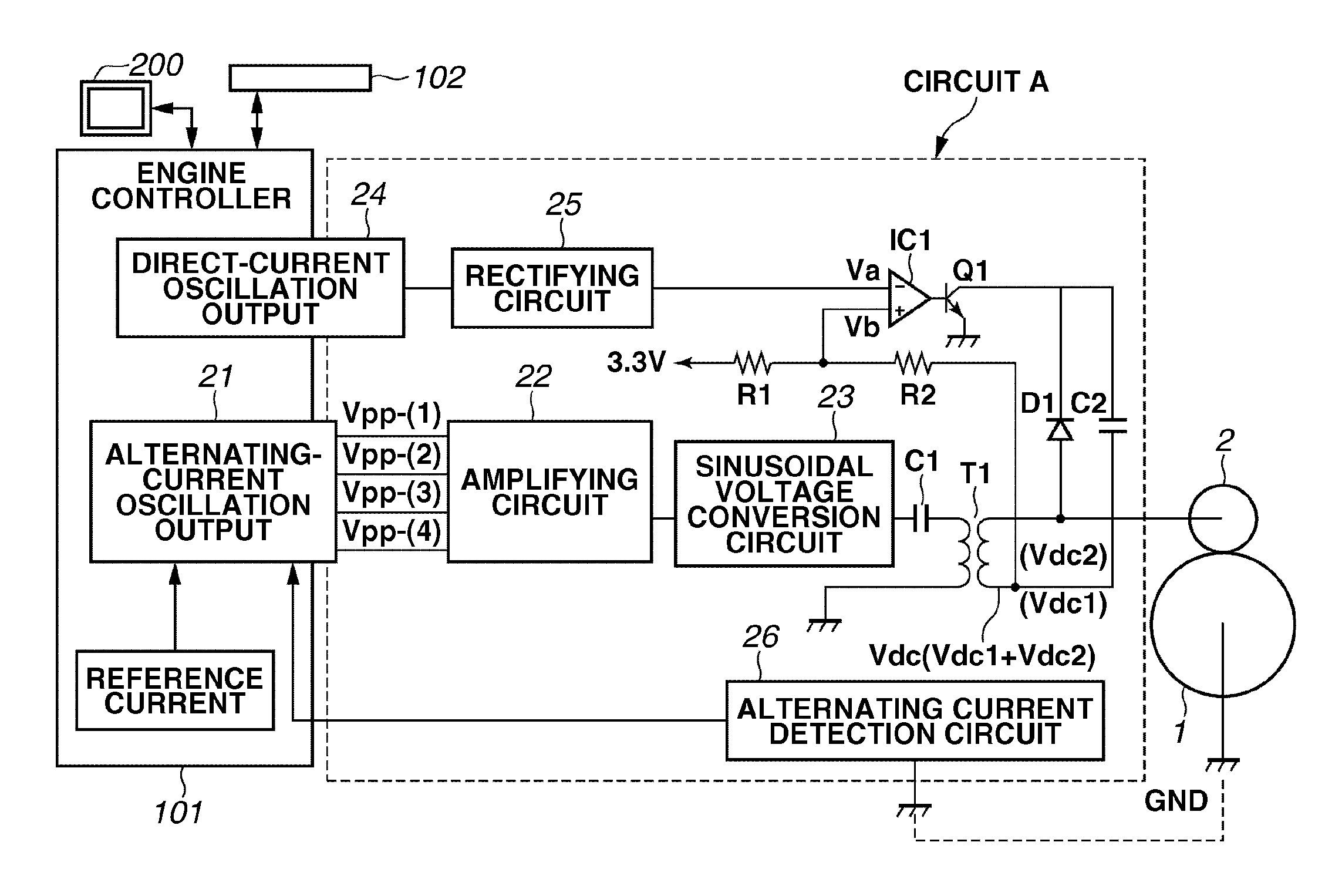
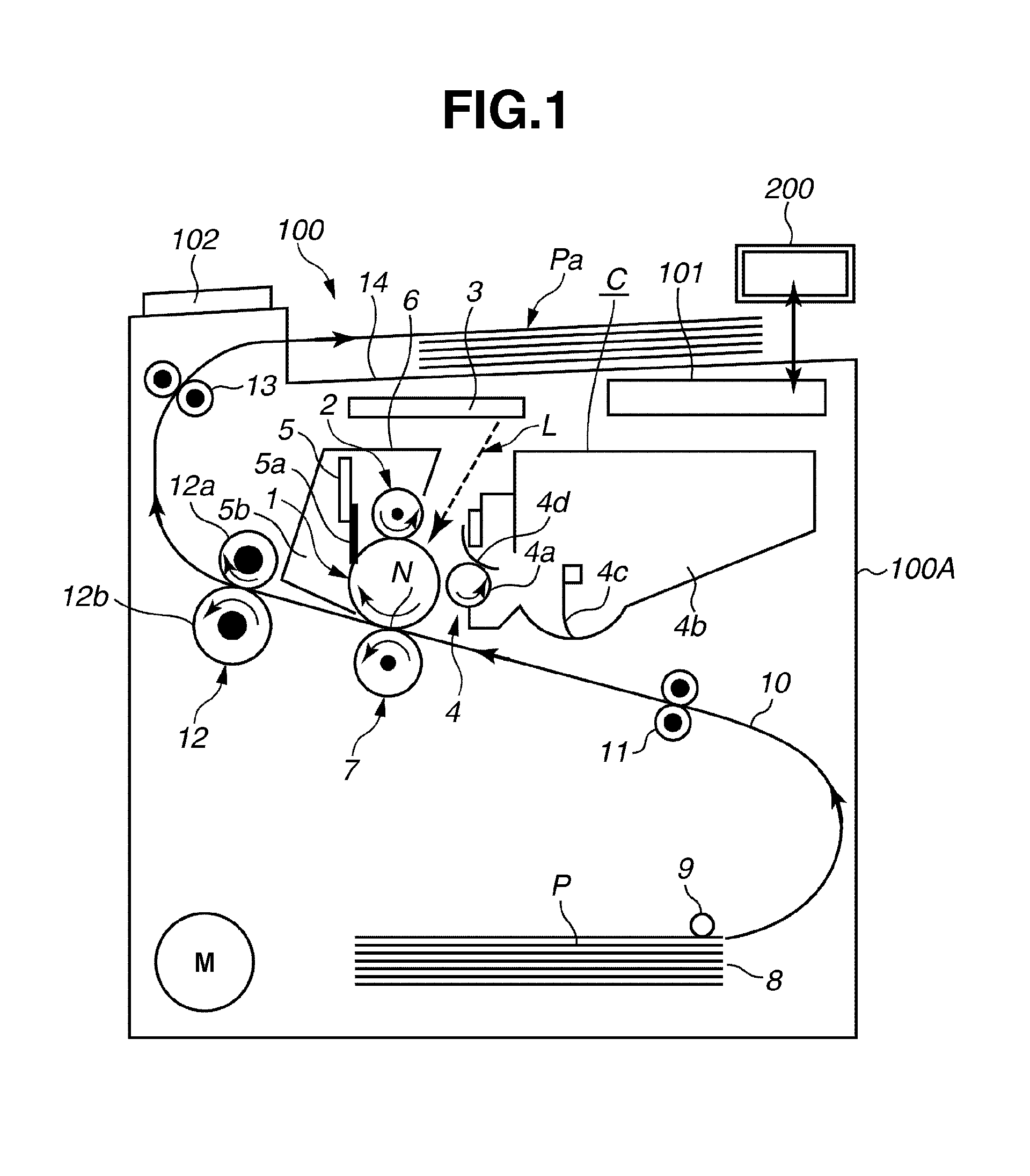
[0022]FIG. 1 is a schematic sectional view of an image forming apparatus 100 according to the first exemplary embodiment. The image forming apparatus 100 is a process cartridge-detachable-type laser printer employing the transfer type electrophotographic process. That is, it is possible to form an image on a sheet-like recording material P and output the same based on electrical image information input to an engine controller (control unit) 101 from a host apparatus 200. The controller 101 controls the operations of the image forming apparatus 100 in general. The controller 101 causes the image forming apparatus 100 to execute image forming operation according to a predetermined image forming sequence in response to a print command from the host apparatus 200 or an operation unit 102. As described below, the image forming apparatus 100 accordin...


PUM


Abstract

An image forming apparatus performs first control, while rotating an image bearing member at a first speed during non-image-formation, to apply a plurality of alternating-current voltages differing in peak-to-peak voltage to a charging device and to detect the value of each alternating current flowing through the image bearing member. When rotating the image bearing member at a second speed during image formation, the image forming apparatus performs second control, while rotating the image bearing member at the second sped before the start of image formation, to apply an alternating-current voltage determined based on the first control to the charging device. In the second control, the image forming apparatus detects the value of the alternating current flowing through the image bearing member, and determines a peak-to-peak voltage of the alternating-current voltage applied to the charging device at the time of image formation based on the detected alternating current value.

Description

BACKGROUND OF THE INVENTION[0001]1. Field of the Invention[0002]The present invention relates to an image forming apparatus employing electrophotography, such as a printer or a copying machine.[0003]2. Description of the Related Art[0004]In an image forming apparatus employing electrophotography, a laser beam corresponding to image information is applied to a uniformly charged photosensitive member, thereby forming an electrostatic latent image. Then, developer is supplied to the electrostatic latent image by a developing unit to make the image visible. Further, the image is transferred from the photosensitive member to a recording material, thereby forming an image on the recording material. A contact charging method using a charging device for the photosensitive member is widely adopted. According to the contact charging method, a charging roller is brought into contact with the surface of the photosensitive member, and voltage is applied to the charging roller to thereby charge t...

Claims


Application Information

Patent Timeline
Patent Type & Authority Applications(United States)
IPC IPC(8): G03G15/02
CPCG03G15/0266
Inventor NOGUCHI, BUNRO
Owner CANON KK
Why Eureka
Try Eureka