Power supply system for vehicle

a power supply system and vehicle technology, applied in the direction of battery/fuel cell control arrangement, propulsion by batteries/cells, instruments, etc., can solve the problems of circuit breakdown, limited selection of motor combinations, etc., and achieve the effect of suppressing system failur

Active Publication Date: 2019-11-28
HONDA MOTOR CO LTD
View PDF0 Cites 8 Cited by
  • Summary
  • Abstract
  • Description
  • Claims
  • Application Information

AI Technical Summary

Benefits of technology

[0024]According to the present invention, it is possible to provide an electric power system of a vehicle, which can appropriately charge a capacitor on a step-down side, and suppress system failure.

Problems solved by technology

There has thereby been a problem in that the selections of combinations of motors are limited such as not being able to combine and use motors of different ratings.
Therefore, by providing a voltage converter between the plurality of motors, a configuration giving a different voltage to each motor has been proposed; however, according to the connection position of the storage battery relative to the voltage converter, there have been problems in that a circuit in which pre-charge is not carried out during connection of the storage battery is produced, and this circuit (fuse, accessory, etc.) may breakdown by a sudden voltage change during drive start of the voltage converter.

Method used


Image

  • Power supply system for vehicle
  • Power supply system for vehicle
  • Power supply system for vehicle

Examples


first embodiment

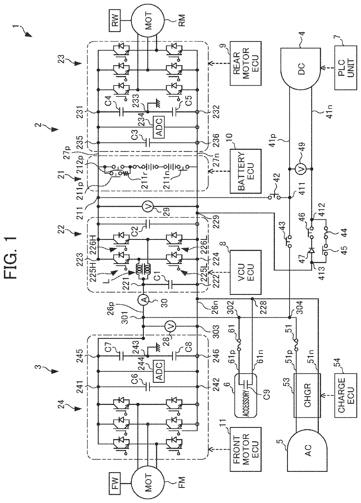
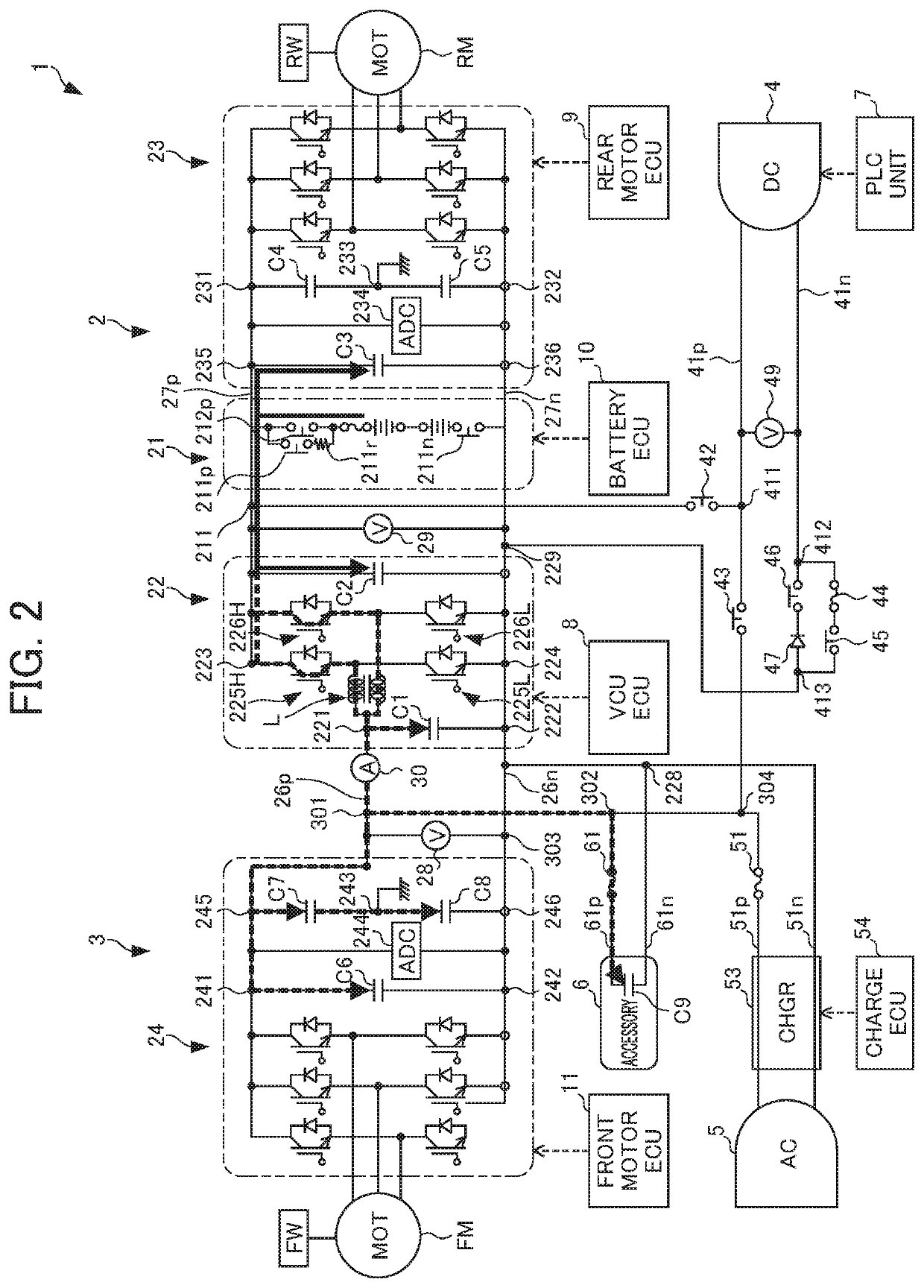
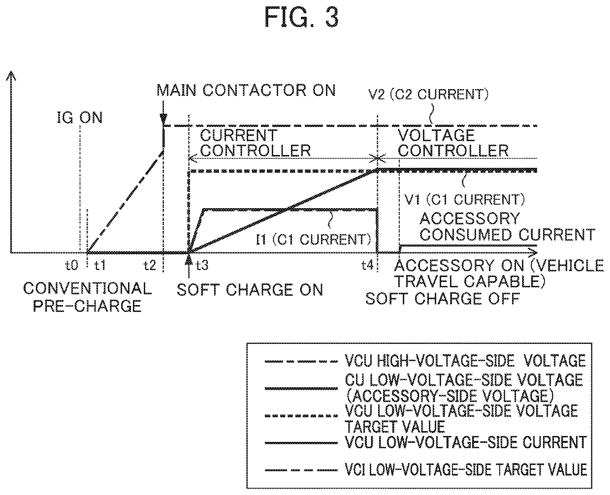
[0055]FIG. 3 is a timing chart of pre-charge according to the At time t0, when ignition turns ON, the VCUECU 8 starts control of electric power. At time t1, pre-charge starts. When the VCUECU 8 sets the contactor 211p to the ON state, current flows to the capacitors C2, C3 in the path shown by arrow A, and the voltage value V2 gradually rises from time t1. At time t2, the VCUECU 8 sets the main contactor 212p to the ON state. At time t3, when setting the switches of the high-arm elements 225H, 226H to the ON state, the electric charge flows to the capacitors C1, C6, C7, C8 and C9 in the path shown by arrow B in FIG. 3. When the VCUECU 8 controls so as to keep constant the current I1 flowing into the capacitor C1 based on the acquired value of the current sensor 30, the voltage value V1 of the capacitor C1 gradually rises. When the capacitor C1 enters the full charge state at time t4, the voltage value V1 reaches a constant value, and the value of current I1 becomes almost 0. The va...

second embodiment

[0058]FIG. 5 is a timing chart of pre-charge according to the At time t0, when the ignition turns ON, the VCUECU 8 starts control of electric power. At time t1, pre-charge starts. When the VCUECU 8 sets the contactor 211p to the ON state, current flows to the capacitors C2, C3 in the path shown by arrow A, and the voltage value V2 gradually rises from time t1. At time t2, the VCUECU 8 sets the main contactor 212p to the ON state. At time t3, when setting the switches of the high-arm terminals 225H, 226H to the ON state, the electric charge flows to the capacitors C1, C6, C7, C8 and C9 in the path shown by arrow B in FIG. 4. The VCUECU 8 controls the current I1 flowing to the capacitor C1, so that the capacitor C1 rises step-wise based on the acquired value of the voltage sensors 28, 29. When the voltage value V1 of the capacitor C1 rises step-wise, and the capacitor C1 reaches the fully charged state at time t4, the voltage value V1 reaches a constant value, and the value of the cu...

third embodiment

[0061]The switching element 400 may be controlled by the VCUECU 8, as a part of the DCDC converter 22. In this case, by the VCUECU 8 turning ON / OFF the switching element 400, it is possible to slowly charge the capacitor C1 by easing the current from the high-voltage battery 21. The switching element 400, upon the element of the top-side arm of the high-voltage DCDC converter 22 short-circuit failing, for example, can suppress the high voltage from being applied to the primary side to which the front motor ECU 11, accessory, etc. are connected. In this way, according to the power supply system for the vehicle it becomes possible to prevent failure of the power supply system 1.

[0062]It should be noted that the equipment called accessory in the aforementioned first to third embodiments may be the DC charging unit 4 capable of charging by DC charging source; voltage sensor 49 which acquires the voltage value applied to the DC charging unit 4 by an external charging device; a high-volt...


PUM


Abstract

To provide a power supply system for a vehicle which can appropriate charge a capacitor on a step-down side, and suppress system failure. The power supply system for a vehicle includes: a high-voltage battery; a first inverter which connects with the high-voltage battery; a drive motor which connects with the first inverter; a high-voltage DCDC converter which steps down the voltage of the high-voltage battery; an accessory, etc. which connects with the high-voltage DCDC converter; a capacitor which connects in parallel with the accessory, etc.; a current sensor, etc. which acquires the charging state of the capacitor; and a VCUECU which controls the high-voltage DCDC converter based on the acquired values of the current sensor, etc.

Description

[0001]This application is based on and claims the benefit of priority from Japanese Patent Application No. 2018-100760, filed on 25 May 2018, the content of which is incorporated herein by reference.BACKGROUND OF THE INVENTIONField of the Invention[0002]The present invention relates to the power supply system for a vehicle.Related Art[0003]Conventionally, a power supply system for a vehicle has been known which performs electric power supply to a plurality of drive motors via a single voltage converter from a battery. The voltage of the battery is converted to a fixed voltage by the voltage converter, and each drive motor is driven by the converted voltage (Patent Document 1).[0004]Patent Document 1: Japanese Unexamined Patent Application, Publication No. 2015-216725SUMMARY OF THE INVENTION[0005]However, with the configuration of Patent Document 1, since the plurality of motors are connected in parallel to the opposite side of the battery relative to the single voltage converter, th...

Claims


Application Information

Patent Timeline
Patent Type & Authority Applications(United States)
IPC IPC(8): B60L53/10B60L53/22G01R31/3842B60L50/51
CPCB60L50/51B60L53/22G01R31/3842B60L2210/12B60L2210/42B60L53/11B60L50/60B60L58/10B60L15/007B60L3/0046B60L2270/20B60L2210/40B60L2220/42B60L3/0023B60L1/00Y02T10/64Y02T10/72Y02T10/70Y02T90/14Y02T10/7072
Inventor TAKEDA, MITSUHIRO
Owner HONDA MOTOR CO LTD
Why Eureka
Try Eureka