

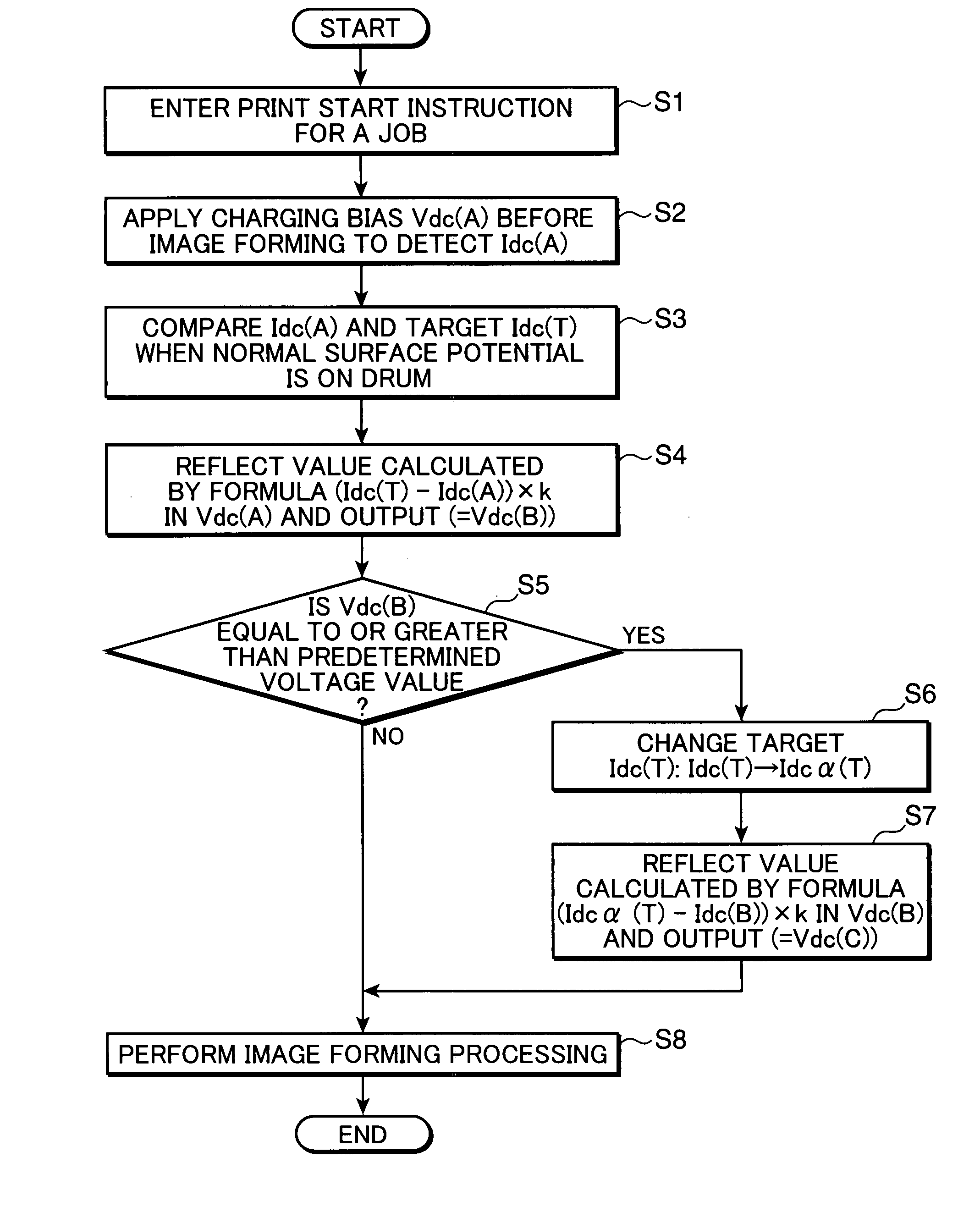
Image forming apparatus with charging bias correcting portion for correcting a charging bias of a charging roller
a charging bias and image forming technology, applied in the field of image forming apparatus, can solve the problems of inability to output appropriate bias, difficulty in accurately detecting charging current, and extremely long time until the start of image forming operation
- Summary
- Abstract
- Description
- Claims
- Application Information
AI Technical Summary
Benefits of technology
Problems solved by technology
Method used
Image

Examples
Embodiment Construction
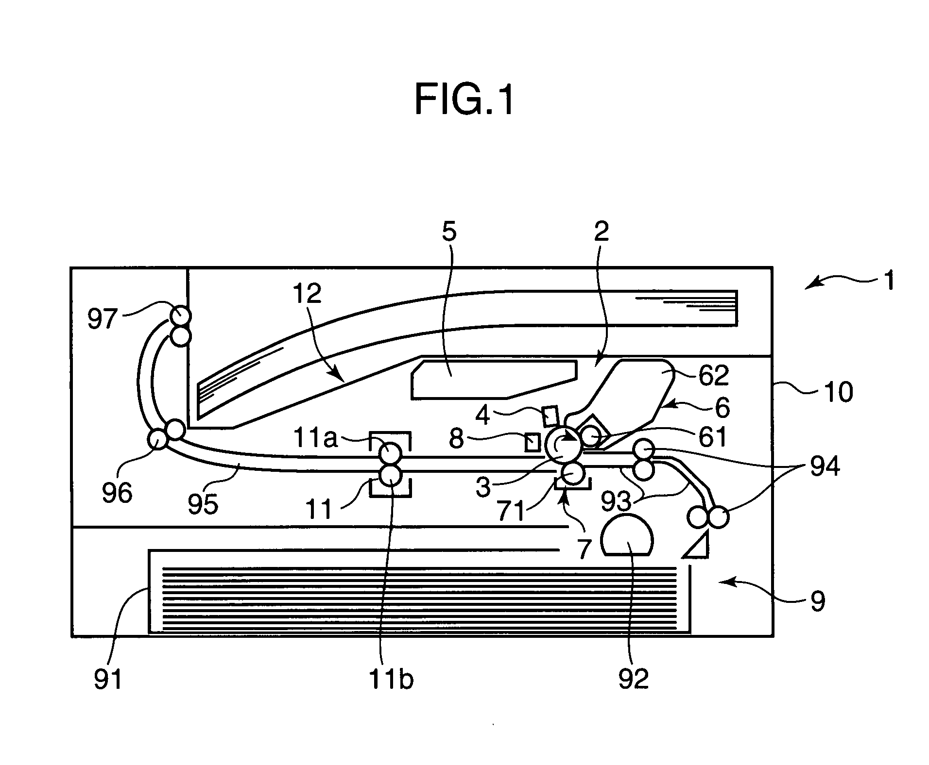
[0017]FIG. 1 is a sectional view that schematically shows the internal configuration of an image forming apparatus according to an embodiment of the present invention. The image forming apparatus according to the present invention is a multifunction device, a printer, a facsimile machine or the like that develops an electrostatic latent image using toner by an electrophotographic method. In the present embodiment, a printer 1 is described as an example of the image forming apparatus. In the printer 1, an image forming portion 2 is provided inside a printer main unit 10. As shown in FIG. 1, the image forming portion 2 performs image formation on a sheet, and includes a photosensitive drum 3, and a charging portion 4, an exposing portion 5, a developing portion 6, a transferring portion 7, and a cleaning portion 8 that are disposed around the photosensitive drum 3.
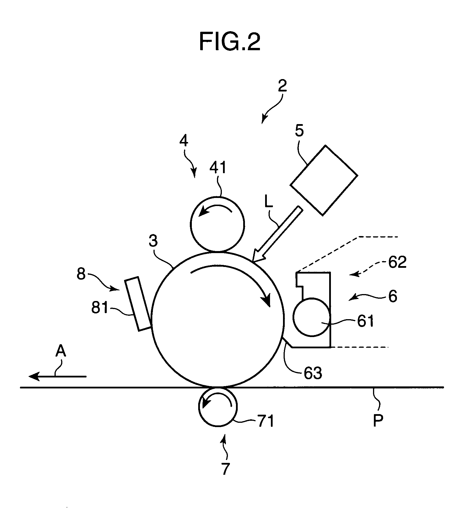
[0018]FIG. 2 is a partial enlarged view that schematically shows the image forming portion 2. The photosensitive drum 3 is...
PUM
 Abstract
Description
Claims
Application Information