Control device for vehicle

a control device and vehicle technology, applied in the direction of propulsion parts, propulsion using engine-driven generators, transportation and packaging, etc., can solve the problems of fuel efficiency degradation, reduce loss, and appropriately perform battery charging or discharging, etc.

Inactive Publication Date: 2018-08-23
TOYOTA JIDOSHA KK
View PDF0 Cites 8 Cited by
  • Summary
  • Abstract
  • Description
  • Claims
  • Application Information

AI Technical Summary

Benefits of technology

[0014]The control device for a vehicle according to the above aspect can select the second traveling mode, the third traveling mode, and the fourth traveling mode according to the vehicle speed in the first traveling mode in which the second rotary machine is separated from the power transmission shaft. For this reason, the control device for a vehicle enables traveling with low loss by separation of the second rotary machine from the power transmission shaft and can appropriately perform charging or discharging of the battery. The control device for a vehicle achieves further reduction in loss during resting of the second rotary machine. In regard to a traveling mode, when an operation of a driver with a high frequency of change, such as change in accelerator opening, is performed, switching control is frequently operated. However, the control device for a vehicle can select the second traveling mode, the third traveling mode, and the fourth traveling mode according to the vehicle speed. Therefore, it is possible to suppress frequent switching of a traveling mode due to the operation of the driver.

Problems solved by technology

However, even if the connection state or the disconnection state between the second motor generator and the power transmission path is switched with excellent responsiveness, if a traveling mode in the connection state or the disconnection state is not appropriate, in this hybrid vehicle, drivability deterioration (insufficient drive force in the driving wheel, degradation of output responsiveness of drive force in the driving wheel, or the like), deterioration of fuel efficiency, or the like may occur.

Method used


Image

  • Control device for vehicle
  • Control device for vehicle
  • Control device for vehicle

Examples


example

[0033]An example of a control device for a vehicle according to the invention will be described referring to FIGS. 1 to 16.

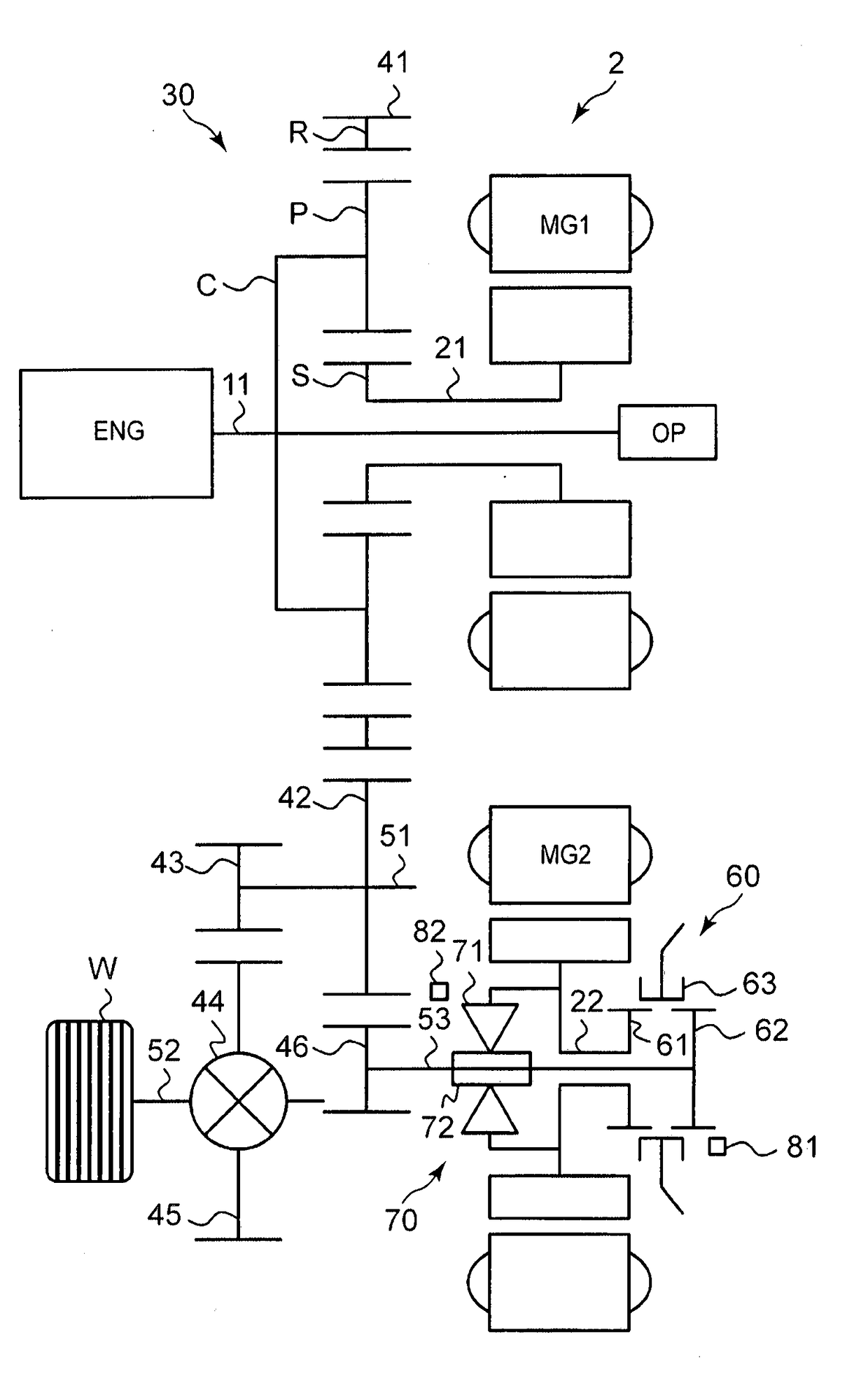
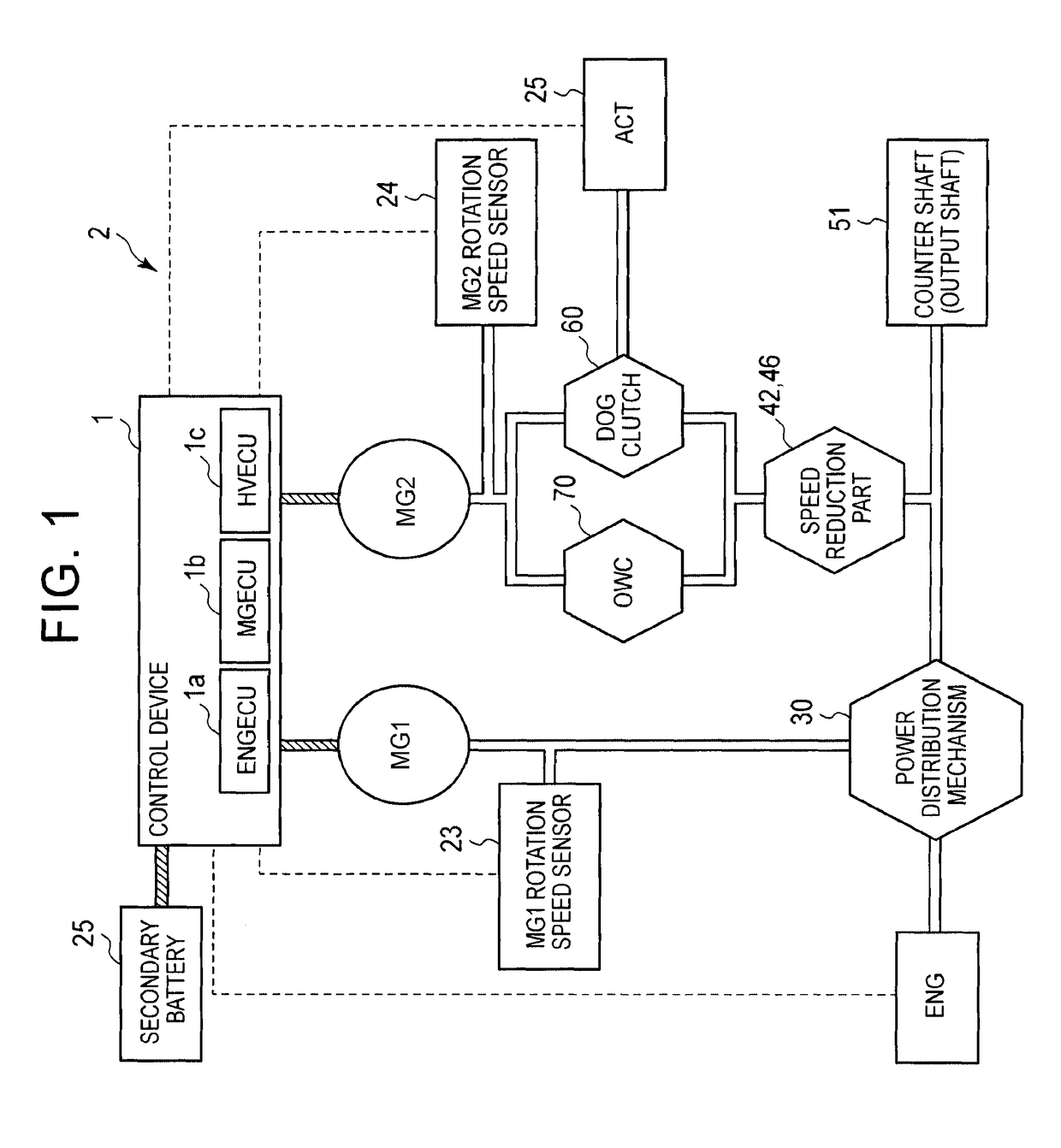
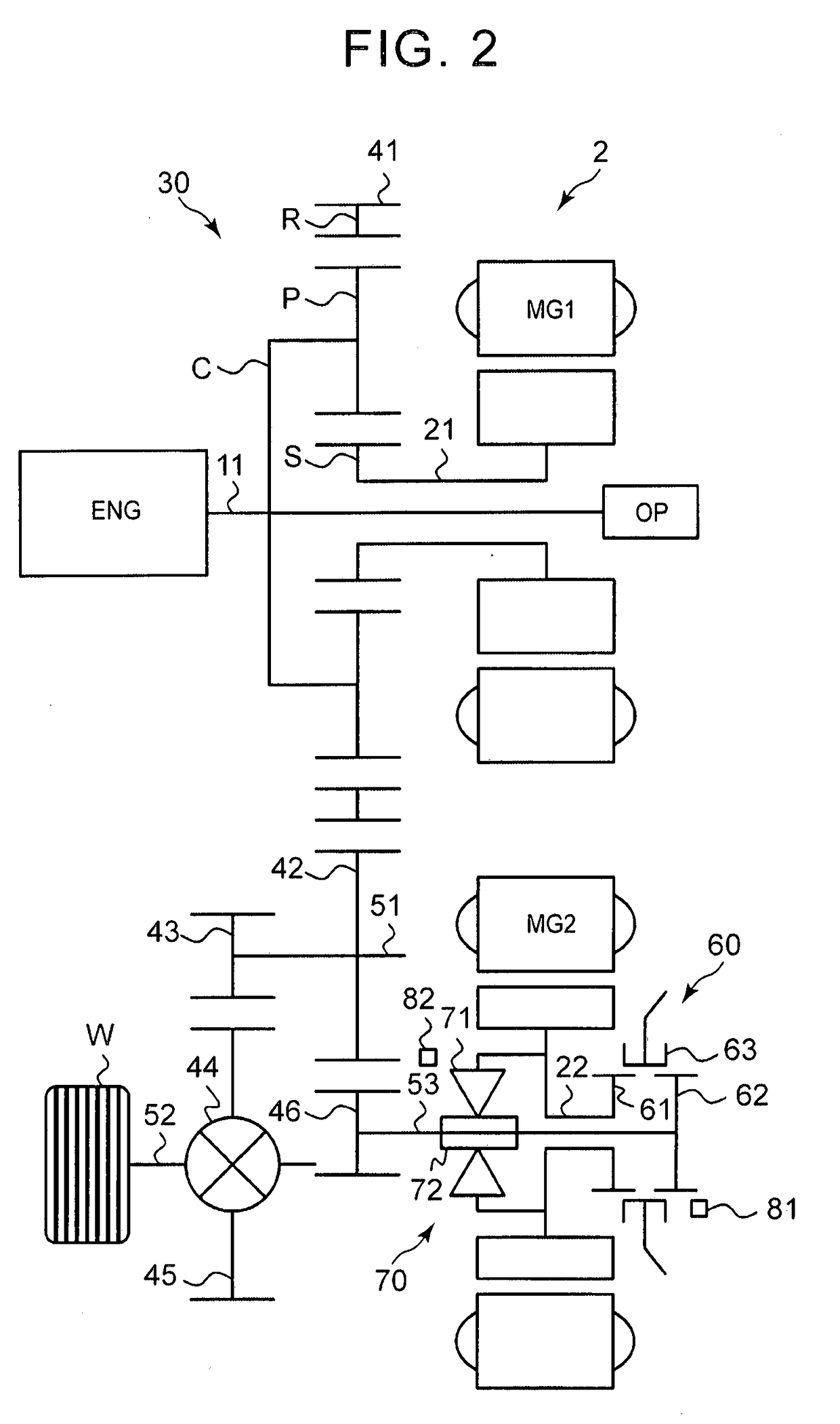
[0034]A vehicle described in this example is a hybrid vehicle which is provided with an engine ENG, a first rotary machine MG1, and a second rotary machine MG2 as a power source. Reference numeral 1 of FIG. 1 represents a control device for the hybrid vehicle. Reference numeral 2 of FIGS. 1 and 2 represents a hybrid system which is mounted in the hybrid vehicle.

[0035]A control device 1 of this example is provided with an electronic control device (hereinafter, referred to as “ENGECU”) 1a which functions as an engine control device configured to control the operation of the engine ENG, an electronic control device (hereinafter, referred to as “MGECU”) 1b which functions as a rotary machine control device configured to control the operations of the first rotary machine MG1 and the second rotary machine MG2, and an electronic control device (hereinafter, referred t...


PUM


Abstract

A control device for a vehicle is provided. The control device includes an ECU. The ECU includes a first traveling mode. The first traveling mode includes a second traveling mode, a third traveling mode, and a fourth traveling mode. The ECU is configured to select the second traveling mode if the vehicle speed is in a low vehicle speed range equal to or lower than a predetermined vehicle speed when the ECU selects the first traveling mode, to select the third traveling mode if the vehicle speed is in a high vehicle speed range equal to or higher than the predetermined vehicle speed, and to select the fourth traveling mode if the vehicle speed is in a vehicle speed range between the low vehicle speed range and the high vehicle speed range.

Description

BACKGROUND OF THE INVENTION1. Field of the Invention[0001]The present invention relates to a control device for a vehicle provided with an engine and a rotary machine as a power source.2. Description of Related Art[0002]In the related art, as this type of vehicle, a hybrid vehicle is known. For example, Japanese Patent Application Publication No. 2013-096555 (JP 2013-096555 A) discloses a hybrid vehicle provided with an engine, a first motor generator, a second motor generator, and a power distribution mechanism having rotary elements, to which the power sources are separately connected. In this hybrid vehicle, the second motor generator is connected to the rotary element of the power distribution mechanism and the driving wheel through a controllable friction clutch and a one-way clutch arranged in parallel. For this reason, in this hybrid vehicle, the friction clutch is released to separate the second motor generator from a power transmission path, or the friction clutch is engage...

Claims


Application Information

Patent Timeline
Patent Type & Authority Applications(United States)
IPC IPC(8): B60W20/20B60K6/383B60K6/387B60K6/445B60W10/02B60W10/06B60W10/08B60W10/26B60W20/14B60L50/16
CPCB60W20/20B60K6/383B60K6/387B60K6/445B60W10/02B60W10/06B60W10/08B60W10/26B60W20/14B60W2510/244B60W2520/10B60W20/40B60W20/00Y02T10/62Y02T10/72B60K6/26B60K6/48B60Y2200/92
Inventor ONO, TOMOHITOENDO, TAKAHITOIWASE, YUJIFUNAHASHI, MAKOTO
Owner TOYOTA JIDOSHA KK
Why Eureka
Try Eureka