Fastener

a technology of fasteners and screws, applied in the direction of fastening means, screws, dowels, etc., can solve the problems of not making the mounting operation easy, and achieve the effect of convenient mounting, easy insertion, and convenient mounting operation

Active Publication Date: 2013-07-25
NEWFREY
View PDF16 Cites 2 Cited by
  • Summary
  • Abstract
  • Description
  • Claims
  • Application Information

AI Technical Summary

Benefits of technology

[0012]These mounting structures and fasteners do not make the mounting operation easy and require metal working, for example, providing a notch in a first member such as a fender panel, in order to engage a fastener. The mounting operation also requires vertical positioning in order to align and insert the fastener into the notch. The object of the present invention is to provide a fastener able to mount a member in another member using a simple mounting operation. More specifically, the object of the present invention is to provide a fastener with a simple mounting operation for mounting structures with difficult portions such as assembling the ends of a panel such as a fender panel in order using bolt fasteners, and for mounting structures that do not require strength but need to prevent panels with seams from popping up.
[0015]In another aspect of the present invention, a sleeve is provided between the rivet insertion hole of the clip and the outer peripheral face of the rivet. This stabilizes the deformation of the plastic clip and the mounting dimensions when the rivet is fastened.
[0016]In another aspect of the present invention, an anti-rotation boss is provided on the side of the second portion of the clip fixed to the second member, the anti-rotation boss being configured so as to be fitted into an anti-rotation mounting hole provided on the second member. This keeps the fastener from rotating with respect to the second member.
[0017]In another aspect of the present invention, the shape of the second portion of the clip on the side fixed to the second member is configured so as to conform to the shape of an anti-rotation depression formed in the second member, and the second portion of the clip is fitted into the anti-rotation depression. This keeps the fastener from rotating with respect to the second member.
[0020]In another aspect of the present invention, the rib provided on the inner side of the second portion of the clip is provided at a predetermined interval from the rivet insertion hole of the second portion so as not to engage the flange-shaped head of the blind rivet during mounting, and the height of the rib is greater than the height of the flange-shaped head. This allows the flange-shaped head to make direct contact with a face on the inner side of the second portion and the rib to make direct contact with a face of the first member.
[0021]In the present invention, the fastener has a C-shaped clip for receiving the first member, the clip has a rivet fixed to the second member, the clip has a first portion, a second portion, and a base joining these portions, and the rivet is configured so as to fix the second portion of the clip to the second member on the side opposite the side clamping the first member. As a result, the first member can be easily mounted on the second member by fixing the fastener to the second member beforehand and then accommodating the first member in the C-shaped clip. When a panel such as a fender panel is mounted and the end is inserted into a gap during assembly, it cannot be fixed inside the gap using a bolt. However, when the fastener of the present invention is set inside the gap beforehand and the end of the fender panel is inserted into the gap, the end of the panel can be easily inserted into the C-shaped clip. As a result, the mounting operation is easier, the fender panel is kept from popping up, and the visible seam is cleaner.

Problems solved by technology

These mounting structures and fasteners do not make the mounting operation easy and require metal working, for example, providing a notch in a first member such as a fender panel, in order to engage a fastener.

Method used


Image

  • Fastener
  • Fastener
  • Fastener

Examples


Embodiment Construction

[0043]The following is an explanation of embodiments of the present invention with reference to the drawings. FIG. 1 through FIG. 12 show a first embodiment of the present invention, and FIG. 13 through FIG. 21 show a second embodiment of the present invention.

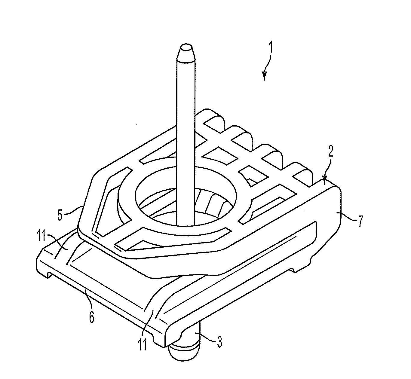
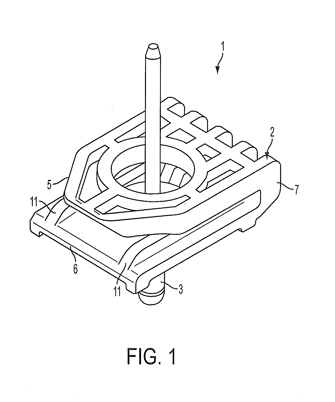
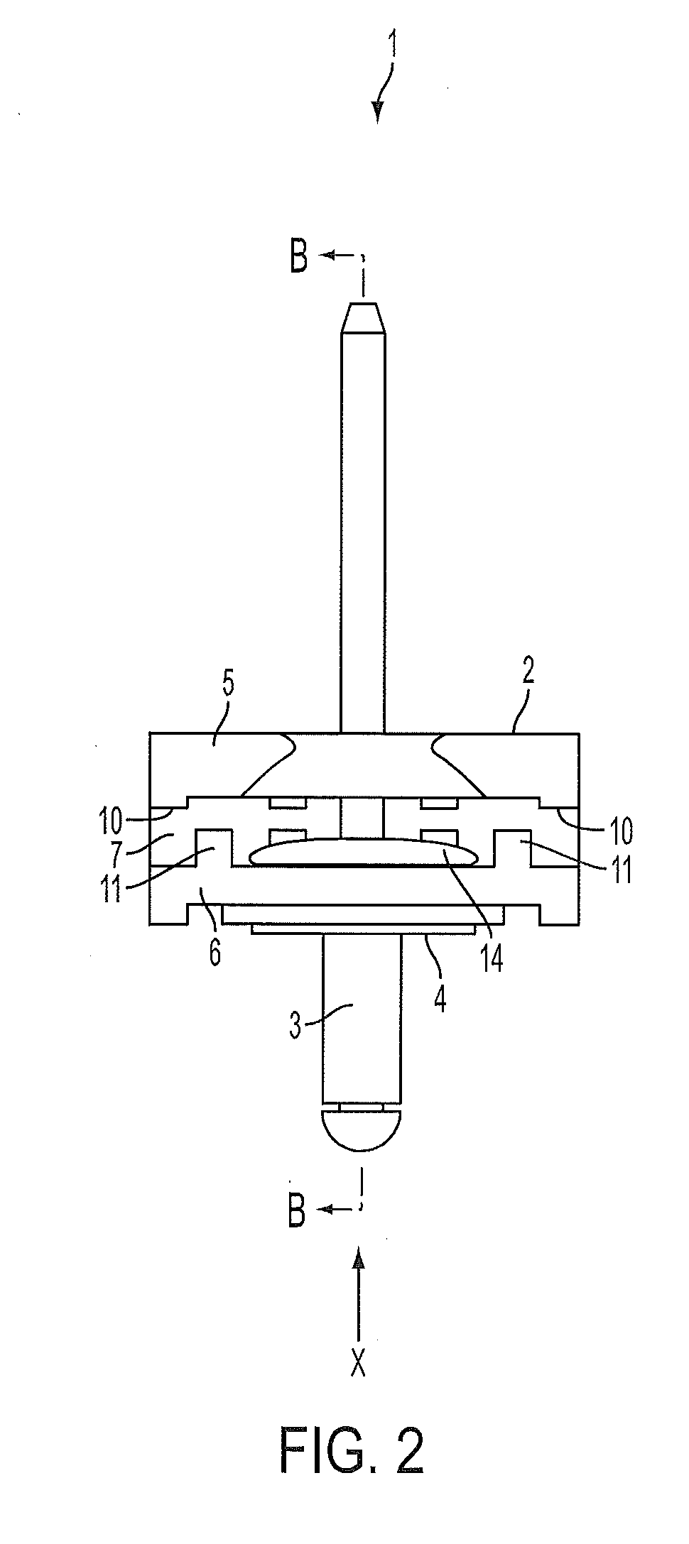
[0044]The first embodiment of the present invention will now be explained. FIG. 1 through FIG. 6 show the fastener 1 in the first embodiment of the present invention, and FIG. 7 through FIG. 10 show details of the plastic clip 2, which is a configurational element of the fastener 1. FIG. 11 shows the fastener 1 in use, and FIG. 12 shows an application of the fastener 1 as a fastener used to mount a fender panel on a body panel.

[0045]As shown in FIG. 6, the fastener 1 has a clip 2, a blind rivet 3, and a sleeve 4. The clip 2 has a first portion 5, a second portion 6, and a base 7 joining the two portions. As shown in FIG. 10, the fastener has a C-shaped cross-section. As shown in FIG. 11, when a clip 2 with this configuration i...


PUM


Abstract

A fastener is fixed to a body panel by inserting a second portion of a clip and the body panel between a flange-shaped head and deformed bulge created by crimping a blind rivet inserted into a mounting hole in the body panel. Afterwards, when a fender panel is inserted between a first portion and the second portion of the clip, pressure is applied to the inserted fender panel from above and below by ribs and on the first and second portions, thereby clamping the fender panel between the first and second portions, and fixing the fastener to the fender panel. The fastener is positioned inside an anti-rotation depression in the body panel.

Description

CROSS-REFERENCE TO RELATED APPLICATIONS[0001]This application claims priority from Japanese Patent Application No. 2012-10139, filed on Jan. 20, 2012, the disclosure of which is incorporated herein by reference.BACKGROUND OF THE INVENTION[0002]The present invention relates to a fastener for mounting a first member such as a fender panel for an automobile to a second member such as a body panel.[0003]A structure for fixing a fender panel to an automobile has been disclosed in Patent Document 1, in which a substantially U-shaped engaging notch is provided in a plate-like lug inside a cutout portion of the fender panel, and the notch engages a deep groove in a fender panel clip mounted on a body panel in order to fix the fender panel to the body panel. The structure for fixing a fender panel to an automobile disclosed in Patent Document 2 is similar to the one disclosed in Patent Document 1.[0004]A bumper side mounting structure has been disclosed in Patent Document 3, in which a clip ...

Claims


Application Information

Patent Timeline
Patent Type & Authority Applications(United States)
IPC IPC(8): F16B19/04
CPCF16B19/04F16B19/1054F16B5/0635
Inventor KATO, HIROYUKI
Owner NEWFREY
Why Eureka
Try Eureka