System and Method for Controlling Redundant Actuators of a Machine

a technology of redundant actuators and control methods, applied in the direction of electric controllers, electric programme control, instruments, etc., can solve the problems of complicated operation of such redundant actuators, and achieve the effect of fast computation times

Active Publication Date: 2013-07-25
MITSUBISHI ELECTRIC RES LAB INC
View PDF3 Cites 60 Cited by
  • Summary
  • Abstract
  • Description
  • Claims
  • Application Information

AI Technical Summary

Benefits of technology

[0011]It is an object of various embodiments of the invention to provide a system and a method for controlling redundant actuators. It is further an object of the invention to control the actuators such that the reference trajectory is accurately traversed during the operations. It is further an object of one embodiment of the invention to coordinate the motions of the redundant actuators such that the reference trajectory is traversed without resulting in mechanical crashes.
[0012]It is further an object of one embodiment of the invention to minimize vibrations resulting from the motions of the redundant actuators. It is further an object of the invention to minimize energy consumed during the operation in traversing the reference trajectory. It is further an object of the invention to guarantee that various mechanical constraints such as velocity, acceleration, and torque limits on the redundant actuators are not violated.
[0013]It is further an object of the invention to control concurrently the motion of the redundant actuators such cross coupling between the actuators is minimized. It is further an object of the invention to provide such a method for controlling the redundant actuators that are tunable in dependence of the requirements and is simple to use.

Problems solved by technology

The operation of such redundant actuators is complicated by the fact that each point on the reference trajectory representing, e.g., a cutting path for a laser cutting machine, can be achieved by various, i.e., not unique, combinations of motions of the redundant actuators.
This fact poses a problem of coordinated control for the redundant actuators, e.g., by determining an optimal sequence of controls for each actuator.

Method used


Image

  • System and Method for Controlling Redundant Actuators of a Machine
  • System and Method for Controlling Redundant Actuators of a Machine
  • System and Method for Controlling Redundant Actuators of a Machine

Examples


Embodiment Construction

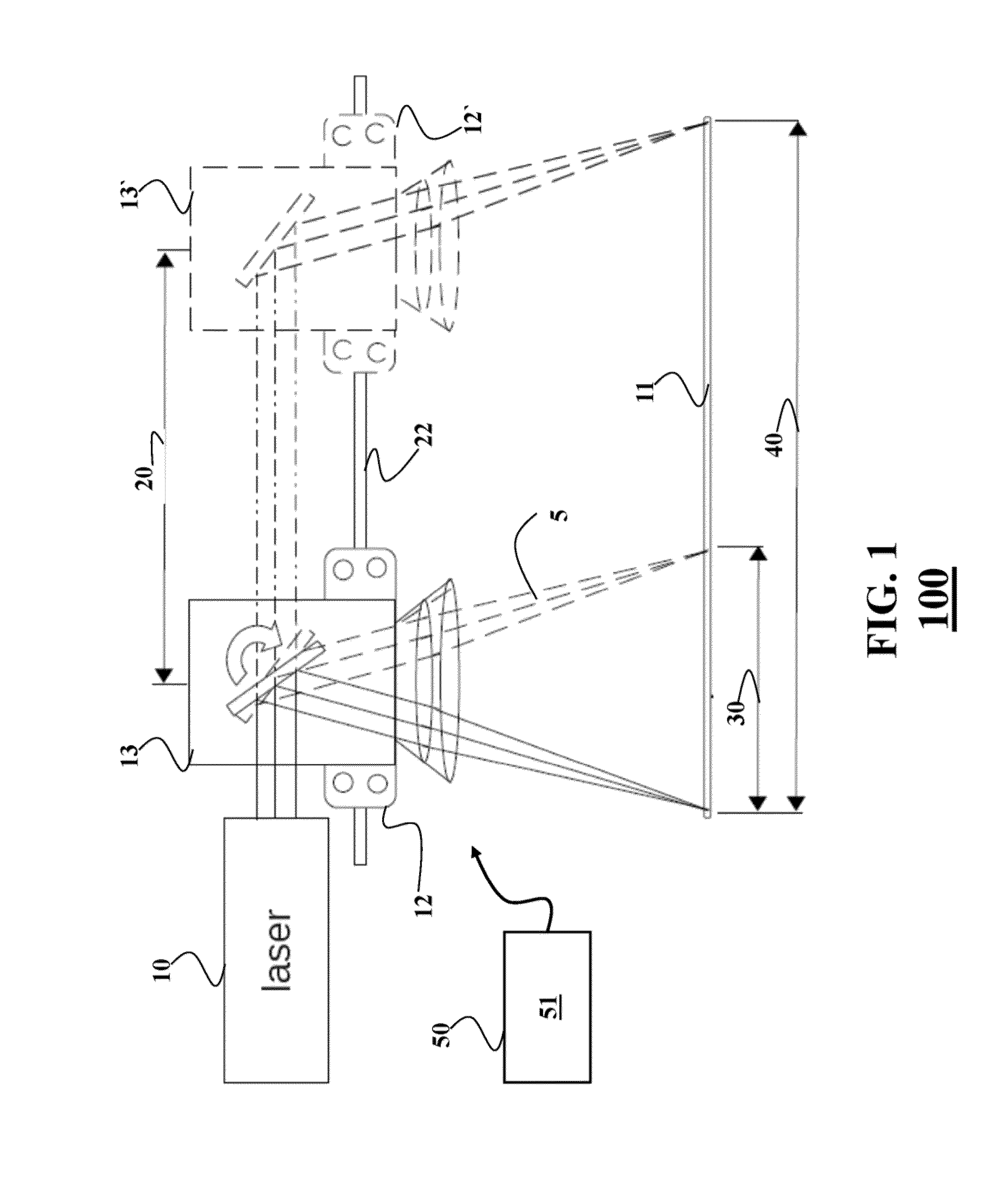
[0044]FIG. 1 shows a block diagram of a machine having redundant actuators. The redundant actuators operate substantially concurrently for at least one direction of motion or operation. An example is a laser cutting machine 100. The laser cutting machine 100 is suitable for controlling a position of a beam produced by a laser 10 on a workpiece 11. The laser cutting machine 100 includes redundant actuators, i.e., a first actuator and a second actuator, such that a laser beam travels along a first direction 20. However, the principles of the invention can be employed by any type of redundant actuators.

[0045]The laser cutting machine includes a first actuator, i.e., a platform 12 configured to move along at least the first direction 20. The platform is moved by a motion system 22 for moving the platform in a plane parallel to the workpiece. In one embodiment, the motion system 22 includes a first prismatic joint facilitating a first motion of the platform along the first direction 20.

[...


PUM


Abstract

A method controls redundant actuators of a machine based on a reference trajectory. The method determines a cost function representing operations of the redundant actuators and minimizes the cost function subject to constraints to produce a sequence of commands for each actuator. The redundant actuators are controlled according to the sequences of commands.

Description

FIELD OF THE INVENTION[0001]This invention relates generally to a system and a method for controlling redundant actuators of a machine, and more particularly to controlling the actuators based on a reference trajectory.BACKGROUND OF THE INVENTION[0002]Common methods for operating laser cutting machines perform two-dimensional (2D) relative motion between a laser beam and a workpiece, such that the laser beam cuts the workpiece as the beam moves. In such machines, there are three options. A position of the laser is fixed and the workpiece is moved in X and Y directions. A position of the workpiece is fixed and the laser or a mirror in the beam path is moved in the X and the Y directions. The laser is fixed in the Y direction and the beam in the X direction, and the workpiece is fixed in X direction and moves in Y direction.[0003]A limiting factor on the production rate of electromechanical machine, such as laser cutting machines, is directly related to the inertia of the components o...

Claims


Application Information

Patent Timeline
Patent Type & Authority Applications(United States)
IPC IPC(8): G06F19/00G05B13/00
CPCG05B19/19
Inventor SHILPIEKANDULA, VIJAYBORTOFF, SCOTT A.
Owner MITSUBISHI ELECTRIC RES LAB INC
Why Eureka
Try Eureka