Bluff body noise control

a technology for reducing noise and body, applied in the direction of airflow influencers, fuselages, transportation and packaging, etc., can solve the problem of significant contribution to the creation of broadband noise, and achieve the effect of reducing nois

Active Publication Date: 2013-08-01
AIRBUS OPERATIONS LTD
View PDF14 Cites 0 Cited by
  • Summary
  • Abstract
  • Description
  • Claims
  • Application Information

AI Technical Summary

Benefits of technology

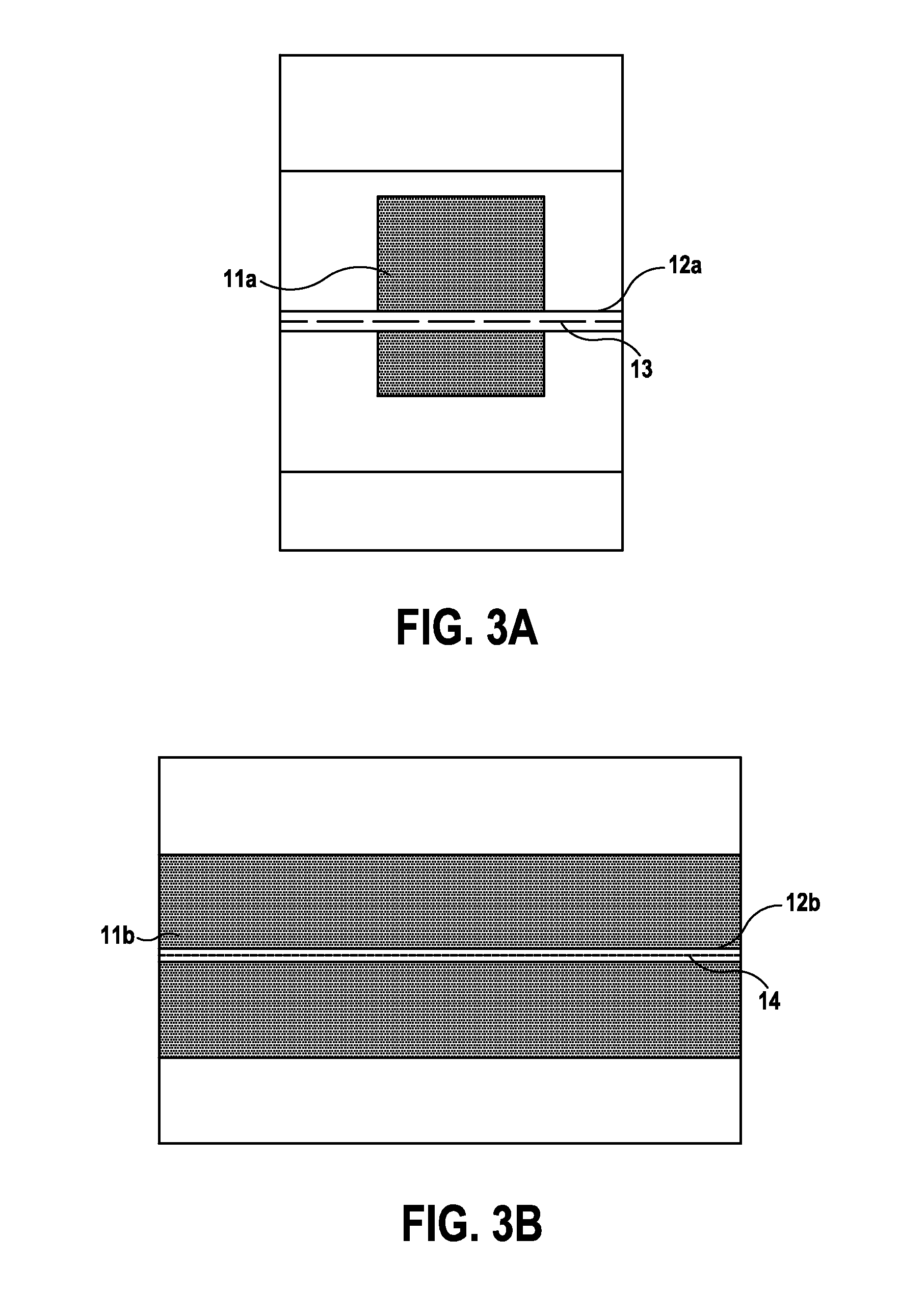
[0006]According to a second aspect of the invention there is provided an aircraft noise-reduction apparatus comprising an aircraft structural element and a flow control device positioned downstream of the structural element and arranged, in use, to reduce noise induced by unsteady flow downstream of the structural element, wherein the flow control device comprises a pneumatic splitter plate. In other words, a jet of air may be blown downstream from the flow-facing element to create an equivalent flow control effect to that of a rigid splitter plate.
[0007]The applicants have found that unsteady flow, around and in the wake of a flow-facing element can cause a significant contribution to creation of broadband noise. In particular, it has been noted that unsteady velocity fluctuations and / or net lift forces generated in the flow may be a key noise generating mechanism. As such embodiments of the invention utilise a splitter plate downstream of the flow-facing element to reduce broadband noise.
[0008]In particular, the flow control device may be arranged to reduce the flow fluctuations due to relatively large scale flow structures in the wake. For example, the flow control device may be arranged to suppress vortex shedding downstream of the flow-facing element.
[0014]According to a second aspect of the invention there is provided an aircraft noise-reduction apparatus comprising an aircraft structural element and a flow control device positioned downstream of the structural element and arranged, in use, to reduce noise induced by unsteady flow downstream of the structural element, wherein the flow control device comprises a pneumatic splitter plate. In other words, a jet of air may be blown downstream from the flow-facing element to create an equivalent flow control effect to that of a rigid splitter plate.
[0017]According to a third aspect of the invention there is provided An aircraft noise-reduction apparatus, the apparatus comprising a fairing, for locating upstream of a structural element such that, in use, airflow is at least partially diverted away from the structural element, and a splitter plate provided in the cavity defined between the fairing and the structural element and arranged, in use, to reduce noise induced by unsteady flow downstream of the fairing. Such an arrangement may help reduce self-noise which may otherwise be produced by the fairing.

Problems solved by technology

The applicants have found that unsteady flow, around and in the wake of a flow-facing element can cause a significant contribution to creation of broadband noise.
In particular, it has been noted that unsteady velocity fluctuations and / or net lift forces generated in the flow may be a key noise generating mechanism.

Method used


Image

  • Bluff body noise control
  • Bluff body noise control
  • Bluff body noise control

Examples


Embodiment Construction

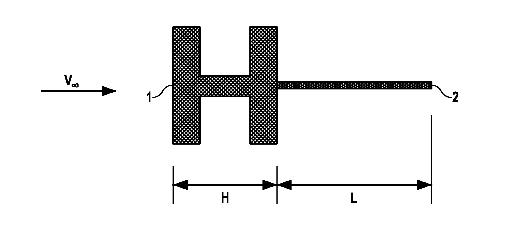
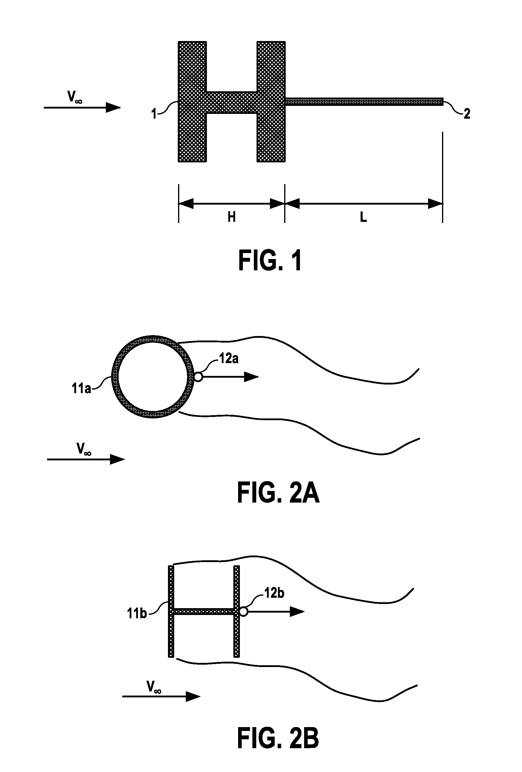
[0028]FIG. 1 shows a noise reduction apparatus in accordance with a first embodiment of the invention. The noise reduction apparatus comprises a structural element 1 which is exposed, in use, to an airflow V∞. In other words, the structural element is flow-facing. V∞ may be assumed to be the free stream airflow. In the case where the structural element 1 is a landing gear component it will be appreciated that it may be deployable, such that it is only be exposed to the airflow V∞ during take-off, landing and approach.

[0029]The structural element 1 is a bluff body, in this case a H-Beam. The skilled person will appreciate that a bluff body may be generally characterised as any body where there is significant flow separation and a generally unsteady wake.

[0030]The noise reduction apparatus further comprises a flow control device in the form of a splitter plate 2. The splitter plate 2 is a rigid plate attached to the downstream side of the structural element 1. The splitter plate 2 ext...


PUM


Abstract

An aircraft noise-reduction apparatus comprise a flow-facing element (1) and a flow control device (2) positioned downstream of the flow-facing element (1). The flow control device (2) is arranged, in use, to reduce noise induced by unsteady flow downstream of the flow-facing element (1).

Description

[0001]This application is a Division of Application No. 12 / 734,334, filed Apr. 26, 2010, which is the US national phase of international application PCT / GB2008 / 050983, filed in English on 23 Oct. 2008, which designated the US. PCT / GB2008 / 050983 claims priority to GB Application No. 0720973.7 filed 26 Oct. 2007. The entire contents of these applications are incorporated herein by reference.FIELD OF THE INVENTION[0002]The present invention relates to noise-reduction apparatus for use on an aircraft. More particularly, but not exclusively, the invention relates to a method of reducing noise generated by the interaction of the landing gear or parts thereof and the air flowing past it during flight, take-off and / or landing.BACKGROUND OF THE INVENTION[0003]Flow around bodies generates noise, which is detrimental in particular aerodynamic applications for example where low noise emissions are a design requirement. One such application where the level of noise emissions is important is in t...

Claims


Application Information

Patent Timeline
Patent Type & Authority Applications(United States)
IPC IPC(8): B64C1/40
CPCB64C21/00B64C23/00B64C25/001B64C2230/14B64C2025/003Y02T50/166B64C1/40B64C25/16Y02T50/10
Inventor CHOW, LEUNG CHOISPITERI, MATTHEWZHANG, XINANGLAND, DAVIDGOODYER, MICHAEL
Owner AIRBUS OPERATIONS LTD
Why Eureka
Try Eureka