Suspension assembly for an automotive vehicle and automotive vehicle comprising such a suspension assembly

a technology for suspension assemblies and automotive vehicles, which is applied in the direction of suspension arms, pivoted suspension arms, transportation and packaging, etc. it can solve the problems of failure, mounting clearance, and failure of suspension arms, so as to eliminate mounting clearance, eliminate bracket wear, and eliminate mounting clearance

Inactive Publication Date: 2013-08-01
VOLVO LASTVAGNAR AB
View PDF4 Cites 8 Cited by
  • Summary
  • Abstract
  • Description
  • Claims
  • Application Information

AI Technical Summary

Benefits of technology

[0005]FR-1 138 218 describes a suspension assembly comprising a bolt mounted through flanges of the bracket and through the suspension arm. Two rubber bushes are mounted, between the bolt and the suspension arm, and pressed against one flange of the bracket by the bolt head. This assembly permits to absorb vibrations between the suspension arm and the bolt and to eliminate the mounting clearance.
[0006]However, this assembly does not prevent wear on the bracket provoked by the head of the bolt inserted in the flange of the bracket.
[0007]It is desirable to provide a suspension assembly for an automotive vehicle, allowing the mounting of the suspension arm with the mounting clearance and the elimination of the clearance by pressing a movable part against the suspension arm, while preventing this part from provoking wear on the bracket, caused by small displacements of the movable part with respect to the bracket.

Problems solved by technology

Wear on the bores of the bracket leads to greater displacements of the suspension arm with respect to the bracket and to failures.
However, this assembly does not prevent wear on the bracket provoked by the head of the bolt inserted in the flange of the bracket.

Method used


Image

  • Suspension assembly for an automotive vehicle and automotive vehicle comprising such a suspension assembly
  • Suspension assembly for an automotive vehicle and automotive vehicle comprising such a suspension assembly
  • Suspension assembly for an automotive vehicle and automotive vehicle comprising such a suspension assembly

Examples


second embodiment

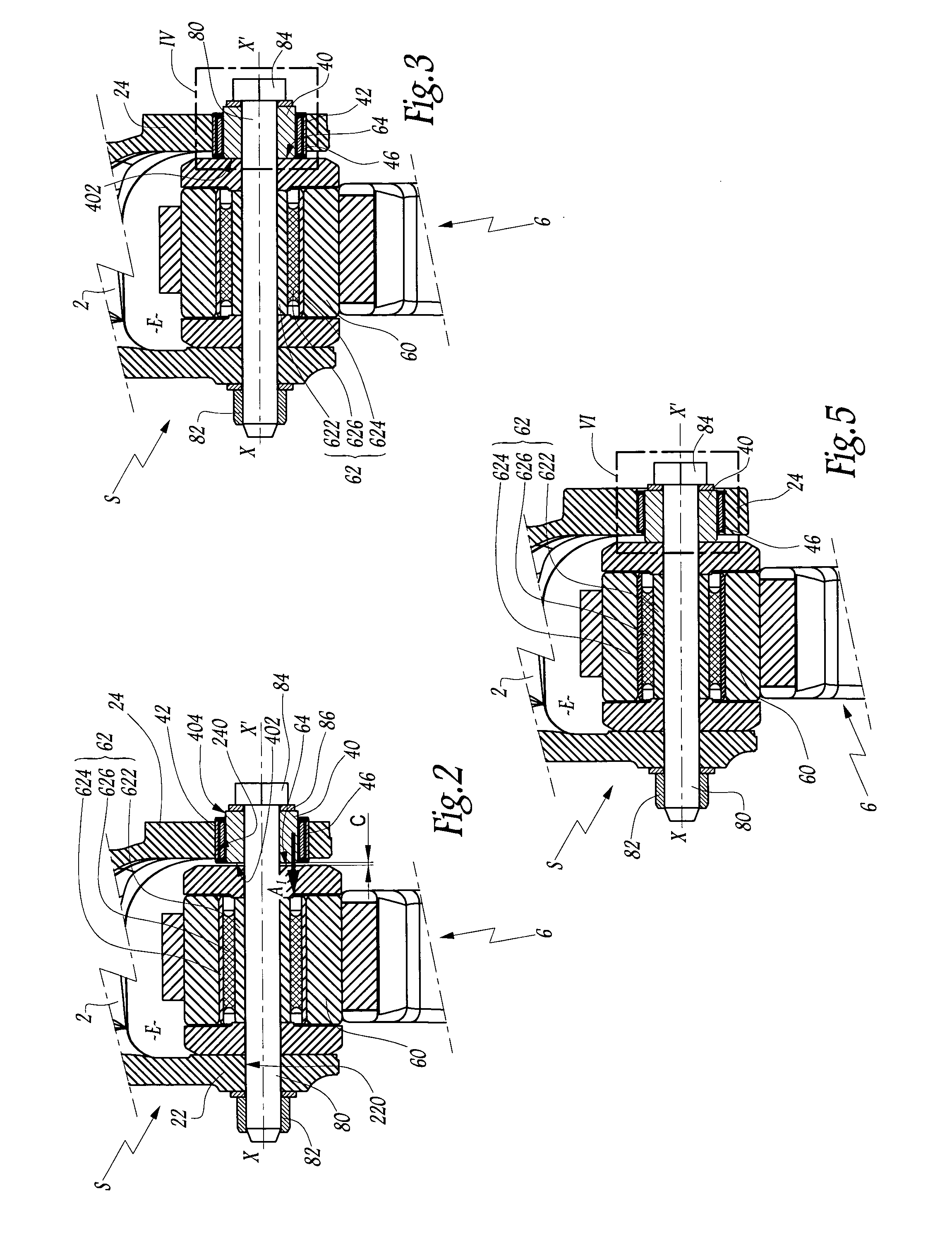
[0055]According to the invention represented on FIGS. 5 and 6, spacer 4 does not comprise any outer ring 42. Deformable sleeve 44 is directly in contact with bore 240 of flange 24. Bore 240 comprises a shoulder 540, extending radially and inwardly towards axis X-X′. This shoulder 540 blocks translation of deformable sleeve 44 with respect to bracket 2 along axis X-X′ and is therefore placed between deformable sleeve 44 and lateral face 64 of suspension arm 6. On its opposite side with respect to shoulder 540, bore 240 comprises a groove 542. An elastic ring 544 similar to elastic ring 49 is mounted in groove 442 to block translation of deformable sleeve 44 with respect to bracket 2 along axis X-X′.

first embodiment

[0056]In this embodiment, mounting of suspension arm 6 in mounting space E of bracket 2 is realized in the same way as in the

[0057]In another embodiment, which is not represented on the figures, shoulder 540 on bore 240 is replaced by an elastic ring similar to elastic ring 48. In that case, another groove similar to groove 542 is provided on bore 240.

[0058]More generally, translations of deformable sleeve 44 along axis X-X′ with respect to outer ring 42 or bracket 2 can be blocked by respective adhesions of sleeve 44 to internal surface 424 or bore240, or by any other blocking means.

[0059]In another embodiment, which is not represented on the figures, deformable sleeve 44 is made of one piece and does not comprise an internal stiffener. The presence or not of stiffener 46 depends on the type of use of the vehicle on which suspension assembly S is mounted. In fact, the size of spacer 4 and more particularly deformable sleeve 44 depends on efforts, displacements and vibrations that s...


PUM


Abstract

A suspension assembly for an automotive vehicle includes a fixed bracket, a suspension arm mounted between two mounting flanges of the bracket, a spacer mounted in a bore of a flange of the bracket, and an articulation shaft mounted through the flanges, the suspension arm. and the spacer. The spacer includes an inner ring in which the articulation shaft is mounted An end face of the inner ring is adapted to be pressed, along a longitudinal axis of the shaft, against a lateral face of the suspension arm. The spacer includes, between its inner ring and the bore in which the spacer is mounted, a deformable sleeve, deformable along die longitudinal axis under a shear effort and adapted to slide with respect to the inner ring or to the bracket, along the longitudinal axis.

Description

BACKGROUND AND SUMMARY[0001]The present invention relates to a suspension assembly for an automotive vehicle. The invention also concerns an automotive vehicle comprising such a suspension assembly.[0002]Automotive vehicles such as trucks are often equipped with suspension systems using leaf springs. Those leaf springs are bound to the vehicle by spring hangers. A leaf spring is generally articulated on a spring hanger at both ends.[0003]Each spring hanger, also named “bracket”, is generally provided with two mounting flanges. A leaf spring, also named “suspension arm”, is mounted between the two flanges. As the suspension arm needs to be mounted with a mounting clearance with respect to the bracket on one side of the suspension arm, the space between the flanges of the bracket is larger than the width of the suspension arm. In normal use, no clearance is allowed between the suspension arm and the flanges of the bracket. The suspension arm is bound with the bracket by a bolt mounted...

Claims


Application Information

Patent Timeline
Patent Type & Authority Applications(United States)
IPC IPC(8): B60G7/02
CPCB60G7/02B60G11/12B60G2202/112B60G2204/121B60G2300/02B60G2204/41B60G2204/4302B60G2206/73B60G2204/143
Inventor BRUN, STEPHANEGUERRA, JULIEN
Owner VOLVO LASTVAGNAR AB
Why Eureka
Try Eureka