Installation structure of cam chain guide apparatus

An installation structure, cam chain technology, applied in the direction of chain/belt transmission, valve device, transmission device, etc., can solve the problems of increasing the friction between the cam chain tensioner and the cam chain, affecting the output power of the engine, and eliminating the need for installation Effects of loosening, impact reduction, and noise reduction

Inactive Publication Date: 2007-10-10
HONDA MOTOR CO LTD
View PDF6 Cites 0 Cited by
  • Summary
  • Abstract
  • Description
  • Claims
  • Application Information

AI Technical Summary

Problems solved by technology

If so, it will inevitably increase the friction between the cam chain tensioner and the cam chain, and affect the output power of the engine

Method used


Image

  • Installation structure of cam chain guide apparatus
  • Installation structure of cam chain guide apparatus
  • Installation structure of cam chain guide apparatus

Examples


Embodiment Construction

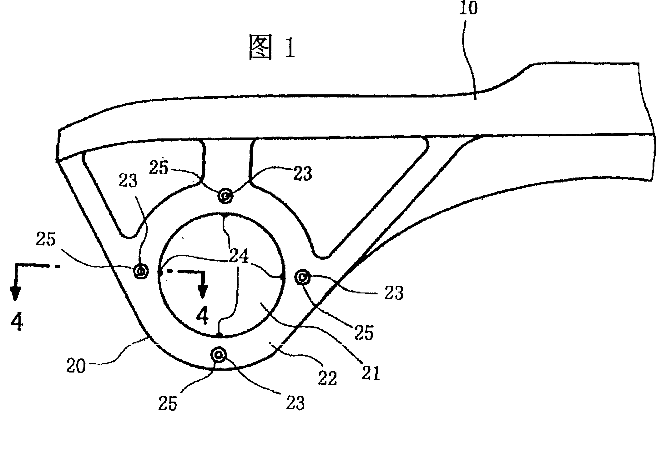
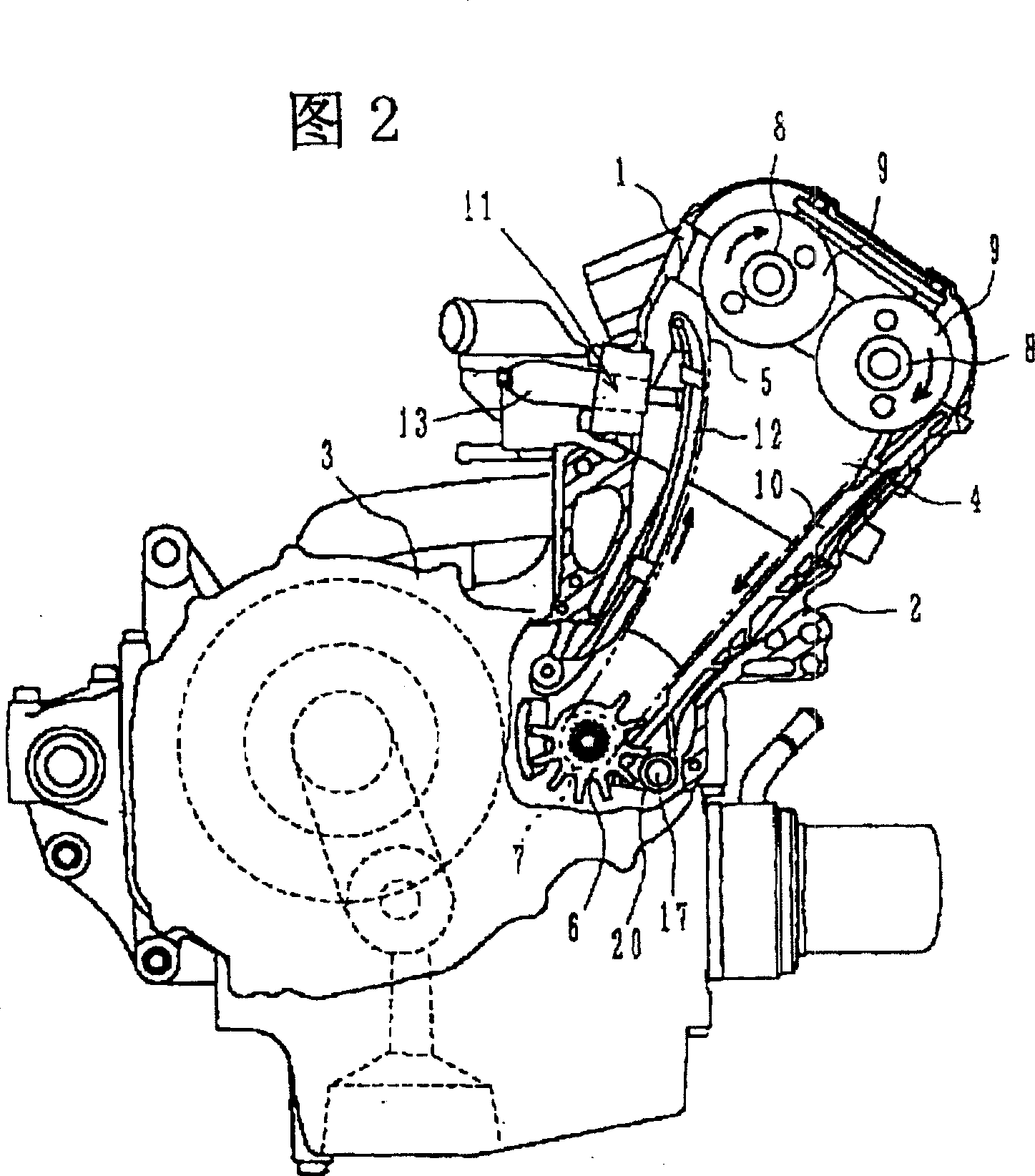
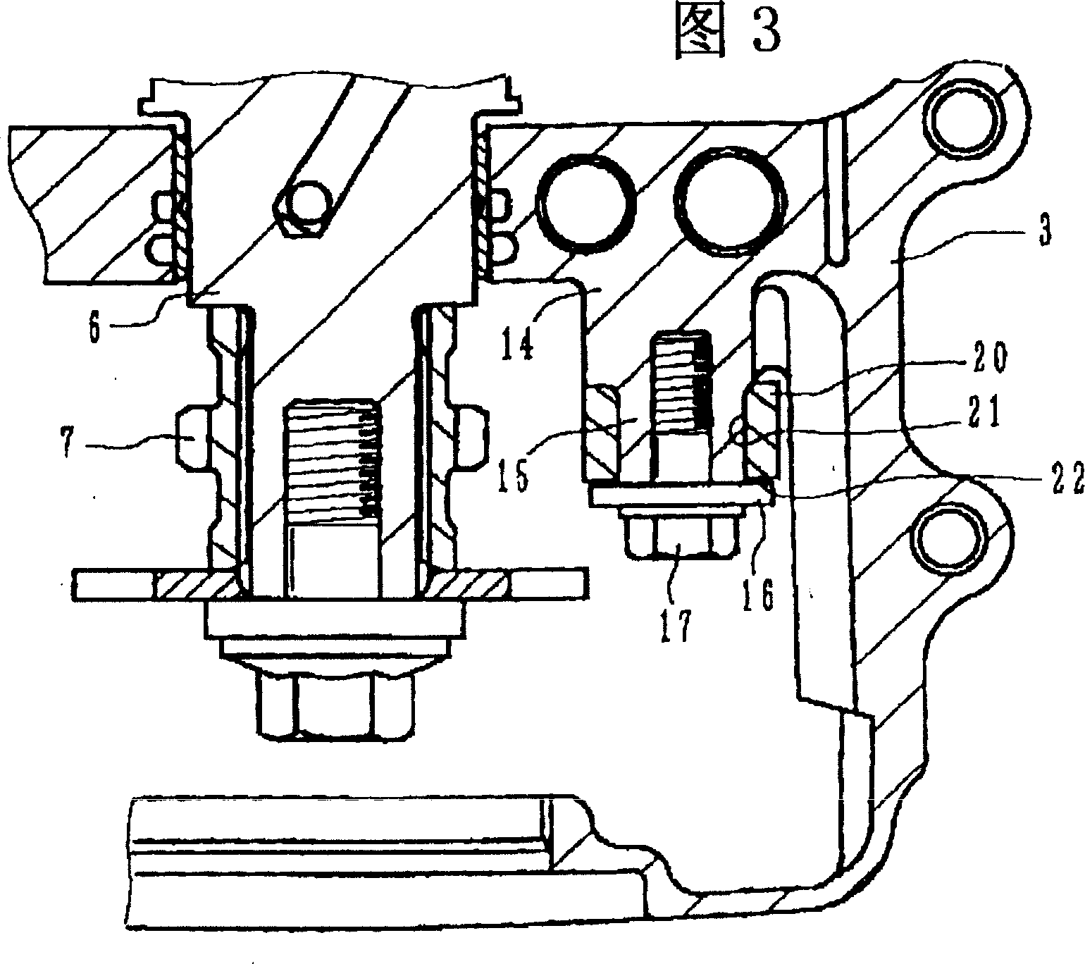
[0021] Below, illustrate an embodiment that is applicable to motor two-wheel vehicle engine by accompanying drawing. Fig. 1 is a side view of the installation end of the indicated cam chain guide viewed from the installation direction; Fig. 2 is a diagram of the engine cut open to show its valve mechanism; Fig. 3 is a diagram of the installation structure of the cam chain guide; Fig. 4 is a cross-sectional view along line 4-4 of Fig. 1; Fig. 5 is a graph showing the noise reduction effect.

[0022] First, the overall schematic structure of the engine will be described with reference to FIG. 2 . This engine is a DOHC 4-cycle engine, 1 is a cylinder head, 2 is a cylinder block, 3 is a crankcase, and a cam chain 5 is accommodated in a cam chain chamber 4 provided on one side of these components.

[0023] The cam chain 5 is wound between the driving sprocket 7 formed on one end of the crankshaft 6 and each cam sprocket 9 on the two camshafts 8, and constitutes a drive transmissio...


PUM


Abstract

To effectively reduce noise caused by an attachment part of a cam chain guide without increasing a pressing force of a cam chain tensioner more than is necessary. A cam chain guide for slidably guiding a cam chain at a valve gear of a four cycle engine is made of resin. An attachment hole for an attachment bolt is provided at an attachment end section for the crankcase. Side surface projections are provided equally spaced at the periphery of an attachment surface surrounding the attachment hole so as to project from a normal surface. Annular recesses are formed at the peripheries of each of the side surface projections. Furthermore, inner surface projections are provided at the inner peripheral surface of the attachment hole equally spaced about the periphery so as to project in a central direction.

Description

technical field [0001] The invention relates to a mounting structure of a cam chain guide on a valve train of a 4-cycle engine. Background technique [0002] On the valve train of a 4-cycle engine, a cam chain guide for slidingly guiding the cam chain and a cam chain tensioner for maintaining tension are provided (as an example, refer to Japanese Patent Application Laid-Open No. 10-77905). At the same time, one end of the cam chain guide is bolted to a mounting member such as a crankcase for support. [0003] However, there is a certain degree of looseness in the support portion of the cam chain guide, and due to this looseness, noise is generated along with the vibration of the cam chain. This noise increases significantly as the engine rotates at high speeds. On the one hand, in order to prevent this kind of noise, it can be considered to adjust the pressure of the cam chain tensioner to strengthen the tension of the cam chain. If so, it will inevitably increase the fri...

Claims


Application Information

Patent Timeline
IPC IPC(8): F16H7/18B62M9/16F02B67/06F01L1/02F16H7/06
CPCF01L1/022F01L1/02F16H7/18
Inventor 岩濑典利手冢义博高桥克德饭冢彻
Owner HONDA MOTOR CO LTD
Why Eureka
Try Eureka