An air filter capable of separating oil and vapor

An oil-vapor separation and air filter technology, applied in the field of air filters, can solve the problems of increased exhaust resistance of crankcases, blue smoke from mufflers, and excessive exhaust emissions, so as to reduce exhaust emissions, prevent waste of oil, and reduce costs. Effect

Active Publication Date: 2016-05-18
ZHEJIANG YAT ELECTRICAL APPLIANCE CO LTD
View PDF6 Cites 0 Cited by
  • Summary
  • Abstract
  • Description
  • Claims
  • Application Information

AI Technical Summary

Problems solved by technology

[0002] At present, there are two main structures for the air filter base and oil-vapor separation methods of general-purpose gasoline engines: the first one is to combine the crankcase exhaust gas and oil vapor that have undergone preliminary oil-vapor separation in the engine cylinder head cover or respirator and a certain amount of oil vapor. A large amount of oil droplets are introduced into the oil-vapor inlet passage of the air filter base, and the oil-vapor inlet passage is generally set above the cylinder intake passage of the air filter base. The problem with this structure is that after preliminary oil-vapor separation The crankcase exhaust gas contains a relatively high proportion of engine oil vapor and oil droplets. The oil vapor and oil droplets will flow along the oil vapor inlet channel with the crankcase exhaust gas or flow into the cylinder intake channel, which will cause the engine to burn oil. The muffler emits blue smoke, the exhaust emission exceeds the standard, and pollutes the environment; the second is to introduce the crankcase exhaust gas and oil vapor and a certain amount of oil droplets that have undergone preliminary oil and vapor separation in the engine cylinder head cover or respirator into the air filter base The oil vapor enters the passage, and the oil vapor enters the passage below the cylinder intake passage of the air filter base. At the same time, an oil return passage is set under the oil vapor entry passage leading to the crankcase, and a check valve is arranged in the oil return passage. , use the negative pressure of the crankcase to suck the excess oil back to the crankcase through the one-way valve of the oil return passage, but the problem with this structure is that there are too many parts for the oil and vapor entering the passage-there are labyrinth composite air guide grooves , Oil baffle plate, oil outlet check valve and valve seat, sealing ring, etc., resulting in complex structure, complex assembly, high cost, and because there are many parts assembled in the oil vapor inlet channel, the crankcase exhaust Increased drag, which reduces the power output of the engine

Method used


Image

  • An air filter capable of separating oil and vapor
  • An air filter capable of separating oil and vapor
  • An air filter capable of separating oil and vapor

Examples


Embodiment Construction

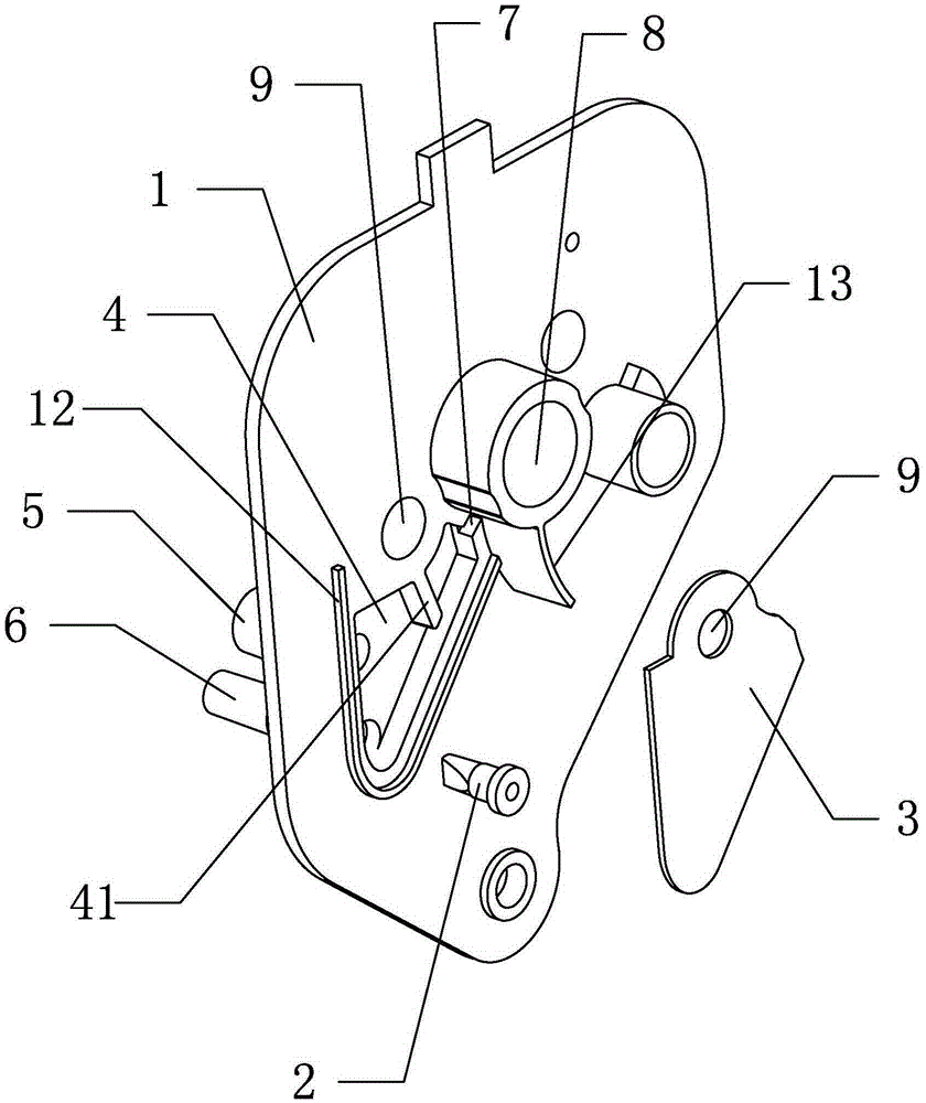
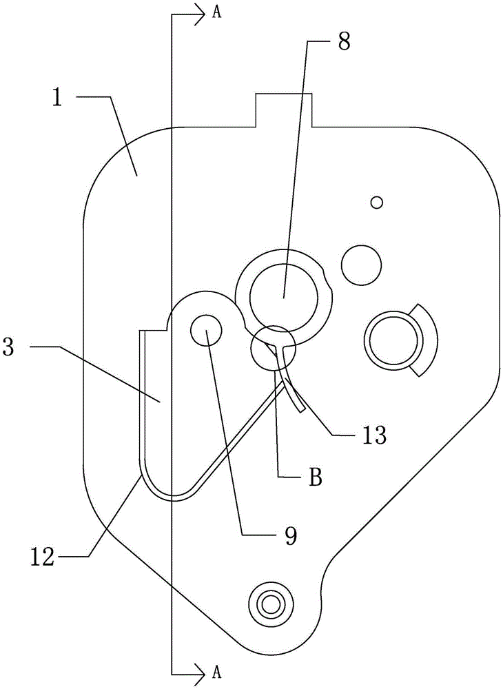
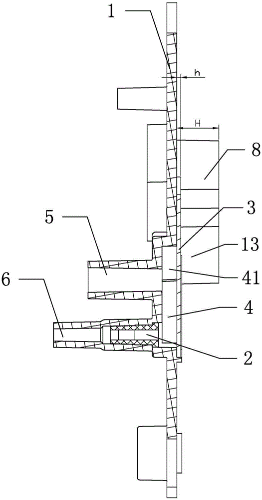
[0019] Such as Figures 1 to 5 As shown, an air filter capable of oil-vapor separation includes a base and an air filter body mounted on the base, wherein the base includes a base body 1 and a baffle 3, and the air filter body is installed on the base body 1 on the baffle 3 On one side, the baffle 3 is closely fitted to the base body 1 and there is a hollow cavity between the two. The close fit is used here to realize the sealing between the baffle 3 and the base body 1 to prevent leakage between the two. Gas, the cavity between the baffle plate 3 and the base body 1 is used as an oil-vapor separation chamber 4 to cool the exhaust gas with oil vapor and oil droplets entering it to separate the oil-vapor (preferably the cavity is a flat cavity, so that after the exhaust gas enters the cavity, the contact effect with the cavity wall is good, and the cooling effect is also good), the side of the base body 1 away from the baffle 3 is provided with an oil vapor inlet channel 5 and ...


PUM


Abstract

The invention provides an air filter capable of separating oil from vapor. The air filter comprises a base. An oil and vapor separation chamber is arranged in the base, an oil and vapor feeding channel and an oil return channel are arranged on one side of the base and are communicated with the oil and vapor separation chamber, an oil return channel check valve which closely clings to the oil return channel is arranged on the oil return channel, an air outlet channel which is communicated with the oil and vapor separation chamber is arranged on the other side of the base, and both the oil and vapor feeding channel and the air outlet channel are higher than the oil return channel. The air filter has the advantages that the oil can be effectively separated from the vapor, so that the engine oil can be prevented from being burned by an engine, resistance generated when oil and vapor are fed into the channel can be reduced, and accordingly output power of the engine is unaffected.

Description

technical field [0001] The invention relates to an air filter capable of separating oil and gas. Background technique [0002] At present, there are two main structures for the air filter base and oil-vapor separation methods of general-purpose gasoline engines: the first one is to combine the crankcase exhaust gas and oil vapor that have undergone preliminary oil-vapor separation in the engine cylinder head cover or respirator and a certain amount of oil vapor. A large amount of oil droplets are introduced into the oil-vapor inlet passage of the air filter base, and the oil-vapor inlet passage is generally set above the cylinder intake passage of the air filter base. The problem with this structure is that after preliminary oil-vapor separation The crankcase exhaust gas contains a relatively high proportion of engine oil vapor and oil droplets. The oil vapor and oil droplets will flow along the oil vapor inlet channel with the crankcase exhaust gas or flow into the cylinder...

Claims


Application Information

Patent Timeline
Patent Type & Authority Patents(China)
IPC IPC(8): F02M35/02F01M13/04
Inventor 聂颖
Owner ZHEJIANG YAT ELECTRICAL APPLIANCE CO LTD
Why Eureka
Try Eureka