Sensor-Activated Transponder

a transponder and sensor technology, applied in the field of transponders, can solve the problems of rescue personnel having to avoid detection of reflected signals, limited range of passive transponders, and lost skiers during off-piste, and achieve the effect of improving directional properties and long detection rang

Inactive Publication Date: 2013-08-01
RECCO INVEST
View PDF3 Cites 53 Cited by
  • Summary
  • Abstract
  • Description
  • Claims
  • Application Information

AI Technical Summary

Benefits of technology

[0008]An object with the present invention is to provide a transponder that has a long detection range compared to p

Problems solved by technology

However, there is a potential risk that skiers are lost and injured during off-piste skiing near trees since voids underneath the snow surface may be formed which are not visible from above.
However, the

Method used


Image

  • Sensor-Activated Transponder
  • Sensor-Activated Transponder
  • Sensor-Activated Transponder

Examples


first embodiment

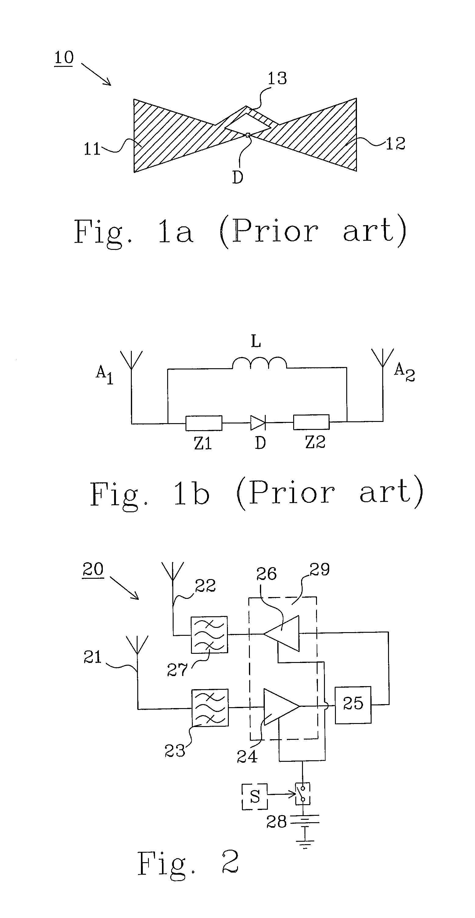
[0032]FIG. 2 shows a transponder 20 comprising an antenna structure with first antenna 21 configured to receive an incoming signal with RF power of a first frequency f1, and a second antenna 22 configured to retransmit the incoming signal as an output signal with RF power of a second, preferably harmonic, frequency. A first frequency filter 23 is connected to the first antenna 21 and is tuned to the first frequency in order to avoid, i.e. prevent or at least reduce the influence of, incoming signals with RF power of frequencies other than the first frequency from being amplified in a first amplifier circuit 24. The amplified incoming signal is thereafter fed to a frequency converter 25 that frequency converts the incoming signal into the output signal, preferably by frequency multiplication of the incoming signal with RF power of the first frequency f1 to obtain an output signal with RF power of a harmonic frequency.

[0033]The output signal is thereafter amplified in a second amplify...

second embodiment

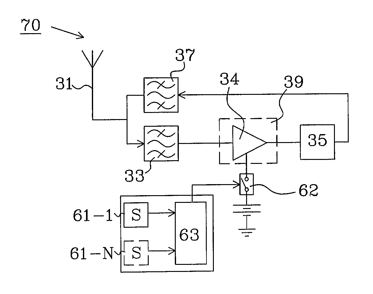
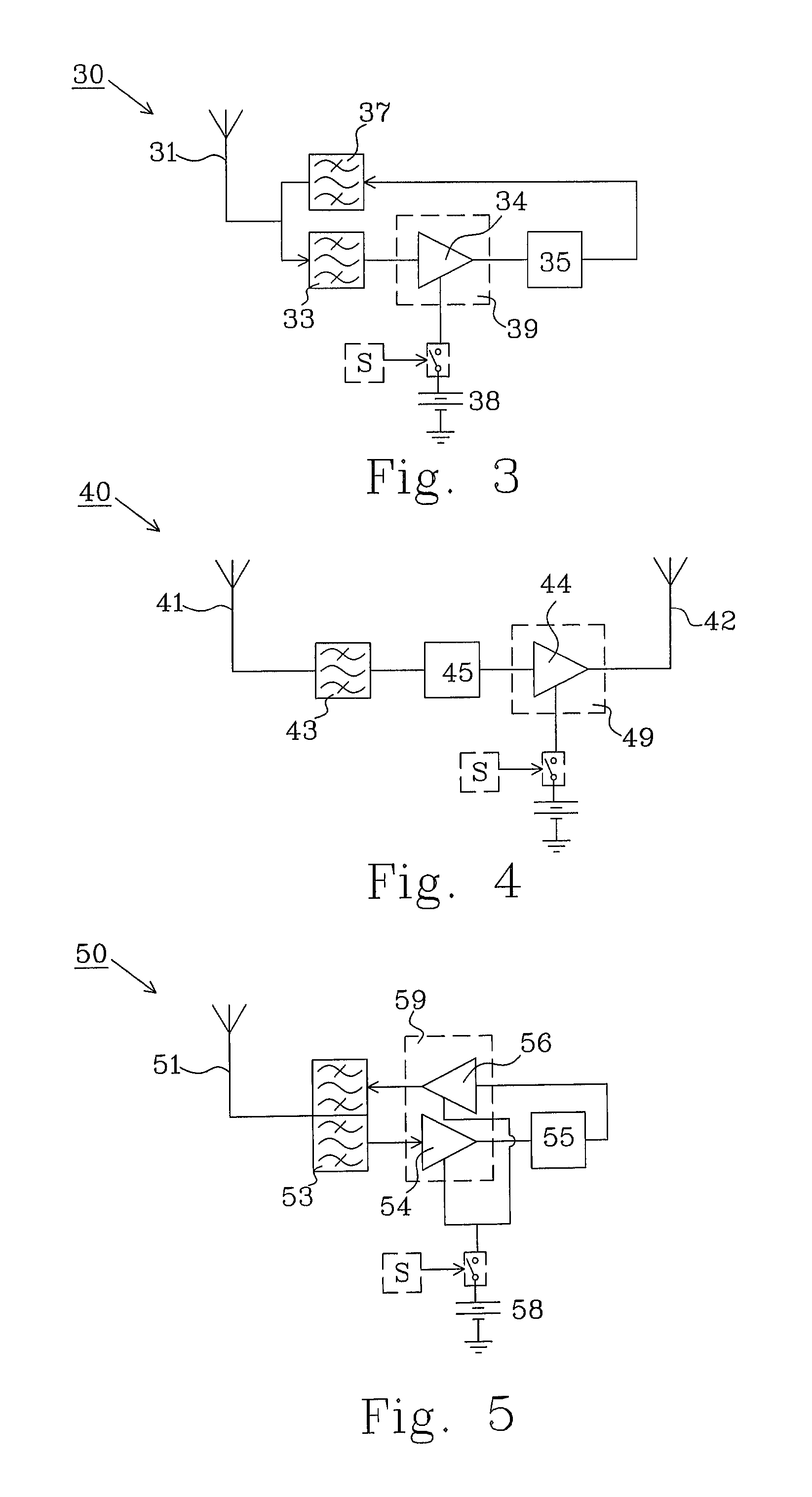
[0034]FIG. 3 shows a transponder 30 comprising an antenna structure with a single antenna 31, which is configured to receive incoming signals having a first frequency f1 and to transmit signals having a second, preferably harmonic, frequency f2. A first frequency filter 33 is connected to the single antenna 31 and is tuned to the first frequency in order to avoid, i.e. prevent or at least reduce the influence of, incoming signals with RF power of frequencies other than the first frequency from being amplified in an amplifier circuit 34. The amplified incoming signal is thereafter fed to a frequency converter 35 that frequency converts the incoming signal into the output signal, preferably by frequency multiplication of the incoming signal with RF power of the first frequency f1 to obtain an output signal with RF power of a harmonic frequency.

[0035]The output signal is, in this embodiment, thereafter filtered in a second frequency filter 37 which is connected to the single antenna 31...

third embodiment

[0036]FIG. 4 shows a transponder 40 comprising an antenna structure with a first antenna 41 configured to receive an incoming signal with RF power of a first frequency f1, and a second antenna 42 configured to transmit an output signal with RF power of a second, preferably harmonic, frequency. A first frequency filter 43 is connected to the first antenna 41 and is tuned to the first frequency in order to avoid, i.e. prevent or at least reduce the influence of, incoming signals with RF power of frequencies other than the first frequency from being frequency converted and thereafter amplified in an amplifier circuit 44. The filtered incoming signal is fed to a frequency converter 45 that frequency converts the incoming signal into the output signal before being fed to the amplifier circuit 44. The frequency conversion is preferably performed by frequency multiplication of the incoming signal with RF power of the first frequency f1 to obtain an output signal with RF power of a harmonic...


PUM


Abstract

The present invention relates to a transponder comprising an antenna structure (31) configured to receive an incoming signal with RF power of a first frequency f1 and to retransmit the incoming signal as a transparent output signal with RF power of a second frequency f2 when hit by the incoming signal. The transponder further comprises: an amplifier (39) configured to provide an amplified transparent output signal based on the incoming signal; a frequency converter (35) configured to frequency convert the incoming signal into the transparent output signal; and a first frequency filter (33) connected to the antenna structure. The first frequency filter is tuned to the first frequency f1 to avoid amplifying incoming signals with RF power of frequencies other than the first frequency f1. The transponder further comprises a sensor (S) configured to respond to physical stimulus for generating a control signal as output response, and an activator for selectively activating or deactivating the possibility to retransmit based on the control signal of the sensor.

Description

TECHNICAL FIELD[0001]The present invention relates to a transponder as defined by the preamble of claim 1.BACKGROUND[0002]Transponders may be used in a variety of applications such as positioning and navigation, e.g. for avalanche rescue and fire rescue missions.[0003]Heliskiing, for example, is a sport in which a helicopter is used to carry skiers to slopes outside the normal ski areas in order for them to ski in deep powder. However, there is a potential risk that skiers are lost and injured during off-piste skiing near trees since voids underneath the snow surface may be formed which are not visible from above.[0004]Today, during avalanche rescue missions, a detector unit is used to detect missing persons that carry passive transponders. The most commonly used type of avalanche rescue equipment is that produced by the Swedish company “RECCO AB”. However, the passive transponders have a limited range. A description of a prior art passive harmonic transponder may be found in U.S. P...

Claims


Application Information

Patent Timeline
IPC IPC(8): G08B23/00
CPCA62B3/00A63B29/021G08B23/00G01S13/767A63B2029/022G01S13/74
Inventor GRANHED, MAGNUSFORSSEN, KARL-GOSTA
Owner RECCO INVEST
Why Eureka
Try Eureka