Battery case lid and manufacturing method for battery case lid

Active Publication Date: 2013-08-01
SOODE NAGANO +1
View PDF1 Cites 18 Cited by
  • Summary
  • Abstract
  • Description
  • Claims
  • Application Information

AI Technical Summary

Benefits of technology

[0032]The battery case lid and the manufacturing method for the battery case lid according to the present invention inhibit work hardening of a metal plate workpiece and fa

Problems solved by technology

When the explosion-proof valve is joined to the substrate section by welding, however, it is difficult to make the thickness of the joining portion uniform.
This gives rise to a problem th

Method used


Image

  • Battery case lid and manufacturing method for battery case lid
  • Battery case lid and manufacturing method for battery case lid
  • Battery case lid and manufacturing method for battery case lid

Examples


Embodiment Construction

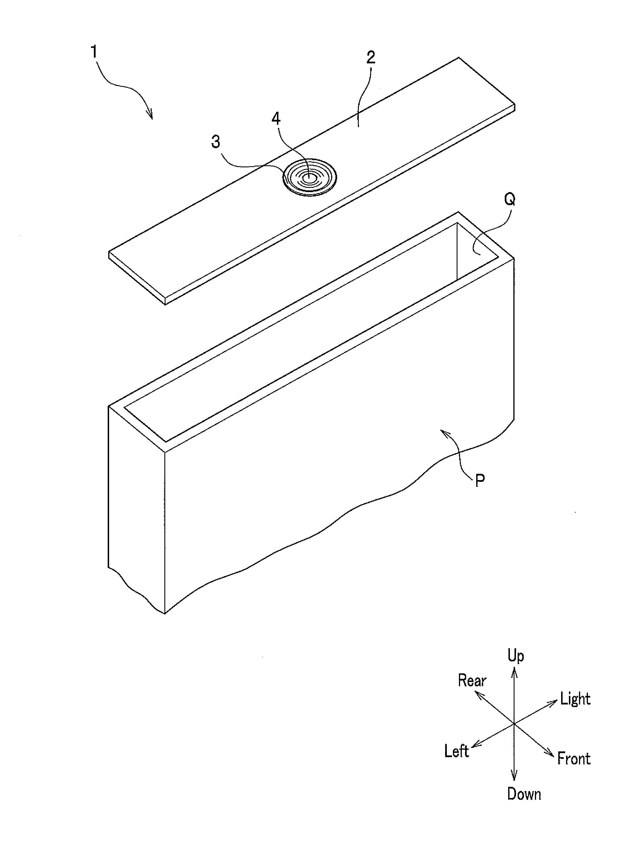
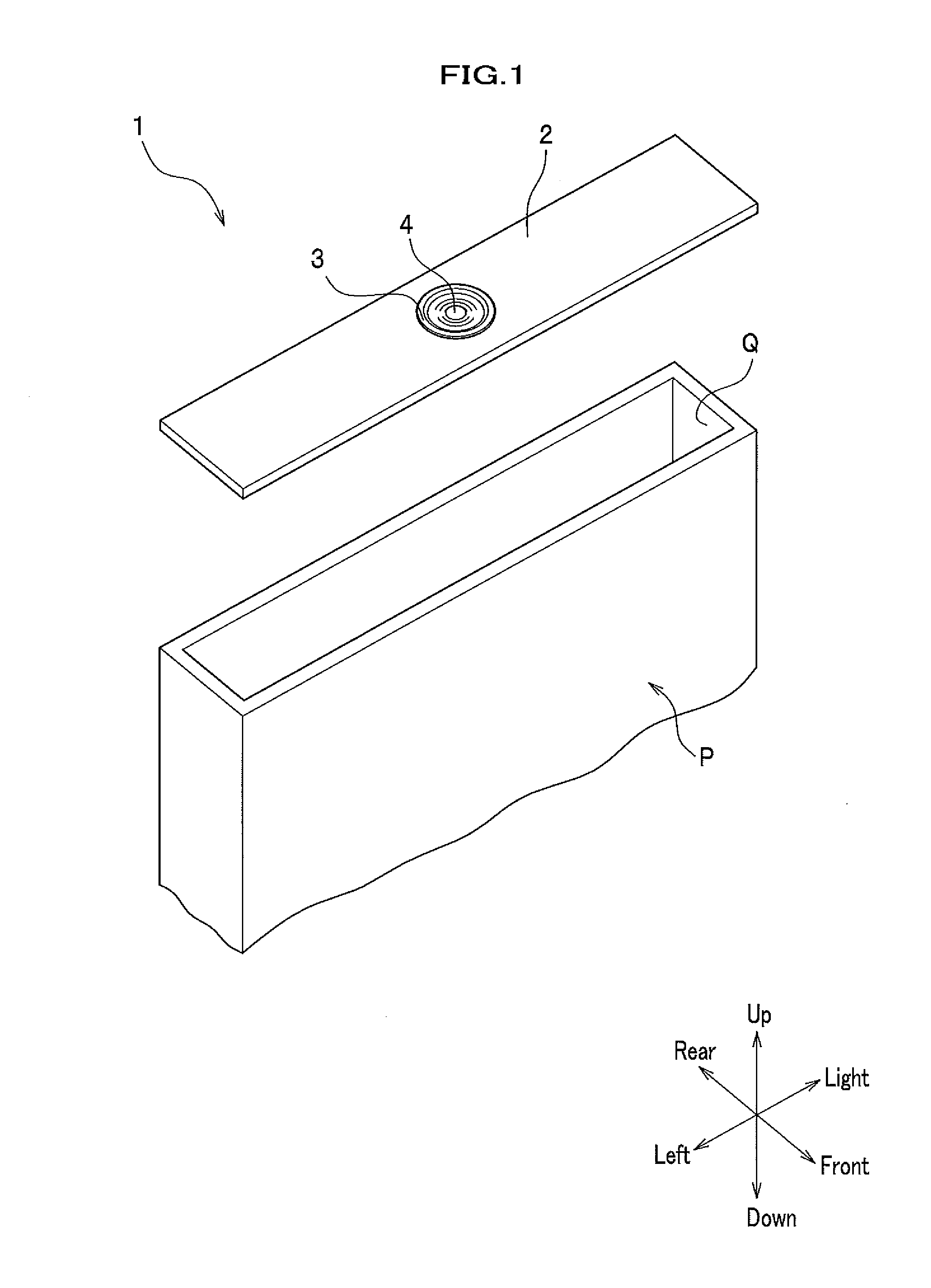
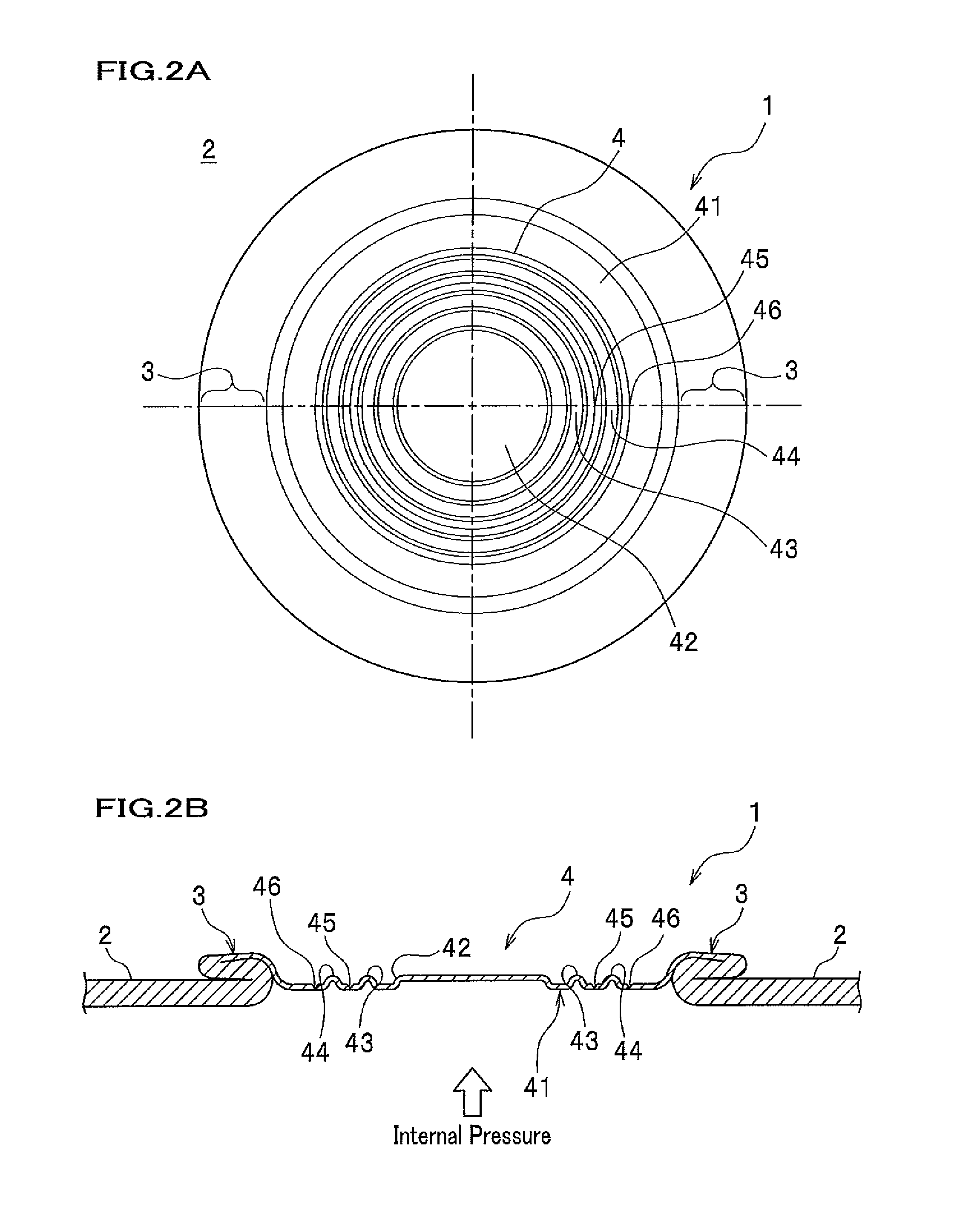
[0051]An embodiment of the present invention will be described in detail with reference to the drawings. First, the configuration of a battery case lid 1 will be described. As shown in FIG. 1, the battery case lid 1 according to the present embodiment is a metal plate member that closes an opening Q of a battery case P for use in a secondary battery. The battery case P is filled with an electrolyte. The battery case P and the battery case lid 1 are welded to each other to hermetically seal the battery case P. In the description, the directions of up, down, right, left, front, and rear are as indicated by the arrows in FIG. 1.

[0052]As shown in FIG. 1, the battery case lid 1 includes a substrate section 2, a folded part 3, and an explosion-proof valve 4. The battery case lid 1 is formed by working a single aluminum alloy plate. The material of the battery case lid 1 is not limited to an aluminum alloy and may be other metals such as copper and iron.

[0053]The substrate section 2 is a f...


PUM

PropertyMeasurementUnit
Thicknessaaaaaaaaaa
Pressureaaaaaaaaaa
Diameteraaaaaaaaaa

Abstract

It is an objective of the present invention to provide a battery case lid and a manufacturing method for the battery case lid which inhibit work hardening of a metal plate workpiece and which facilitate manufacture of a battery case lid. Provided is a battery case lid (1) formed by working a metal plate, including: a substrate section (2) and an explosion-proof valve (4) formed in the substrate section (2), wherein the explosion-proof valve (4) has a reduced thickness section (41) thinner than the substrate section (2), and the reduced thickness section (41) is formed by extending the metal plate by applying pressure while the metal plate is kept unrestrained.

Description

TECHNICAL FIELD[0001]The present invention relates to a battery case lid for use in a secondary battery.BACKGROUND ART[0002]Secondary batteries comprise, for example, a battery case containing an electrolyte and a battery case lid closing an opening of the battery case. The battery case lid mainly includes a substrate section welded to the battery case and an explosion-proof valve for releasing the internal pressure from inside the battery case when abnormality occurs to the electrolyte. The explosion-proof valve is thinned compared to the substrate section and designed to rupture when the internal pressure exceeds a predetermined value.[0003]Conventionally, in a case where the explosion-proof valve is formed, the explosion-proof valve is joined to the substrate section by, for example, welding. When the explosion-proof valve is joined to the substrate section by welding, however, it is difficult to make the thickness of the joining portion uniform. This gives rise to a problem that...

Claims


Application Information

Patent Timeline
IPC IPC(8): H01M2/12B21D51/38
CPCB21C23/186B21D11/08B21D51/44B21D51/383H01M2/0426H01M2/1241B21K23/00Y02E60/10H01M50/169H01M50/3425
Inventor SODE, TAKAYUKISUGIYAMA, YUKINORINOMURA, SHINICHIKOBAYASHI, MASATO
Owner SOODE NAGANO
Why Eureka
Try Eureka