Flow sensor arrangement

a sensor arrangement and flow sensor technology, applied in the direction of volume/mass flow measurement, measurement devices, instruments, etc., can solve the problems adversely affecting the flow sensor itself, and the general tendency of the bypass to be more susceptible to contamination, so as to accurately represent the actual flow, the effect of increasing the flow resistance and improving the measurement results

Active Publication Date: 2013-08-08
SENSIRION AG
View PDF3 Cites 9 Cited by
  • Summary
  • Abstract
  • Description
  • Claims
  • Application Information

AI Technical Summary

Benefits of technology

[0007]As a result, fewer particles may enter the bypass, such that the flow resistance in the bypass may not be increased by such particles and the flow sensor may not be adversely affected by such particles either. Overall, the measurement results may be improved and may more accurately represent the actual flow in the bypass and the main channel respectively.

Problems solved by technology

Hence, the bypass generally is more susceptible to contamination.
Such particles may either become stuck in the bypass and, therefore, increase the flow resistance in the bypass or adversely impact the flow sensor itself.
Both alternatives lead to incorrect measurement results which do not represent the real flow in the bypass and the main channel respectively.

Method used


Image

  • Flow sensor arrangement
  • Flow sensor arrangement
  • Flow sensor arrangement

Examples


Embodiment Construction

[0013]Similar or relating components in the several figures are provided with the same reference numerals.

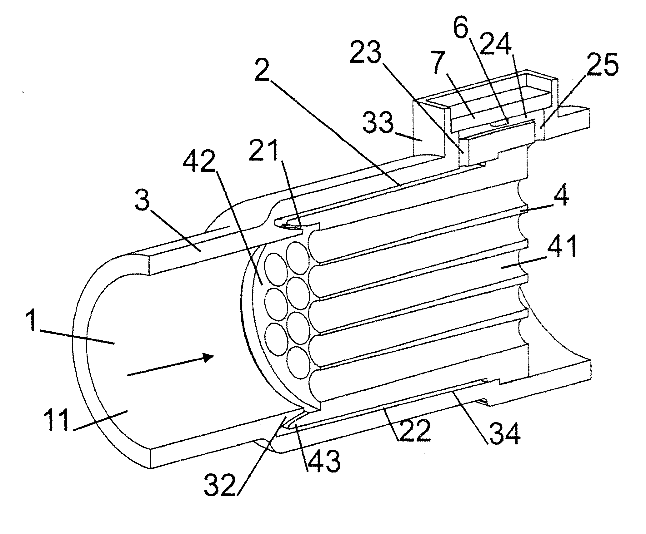
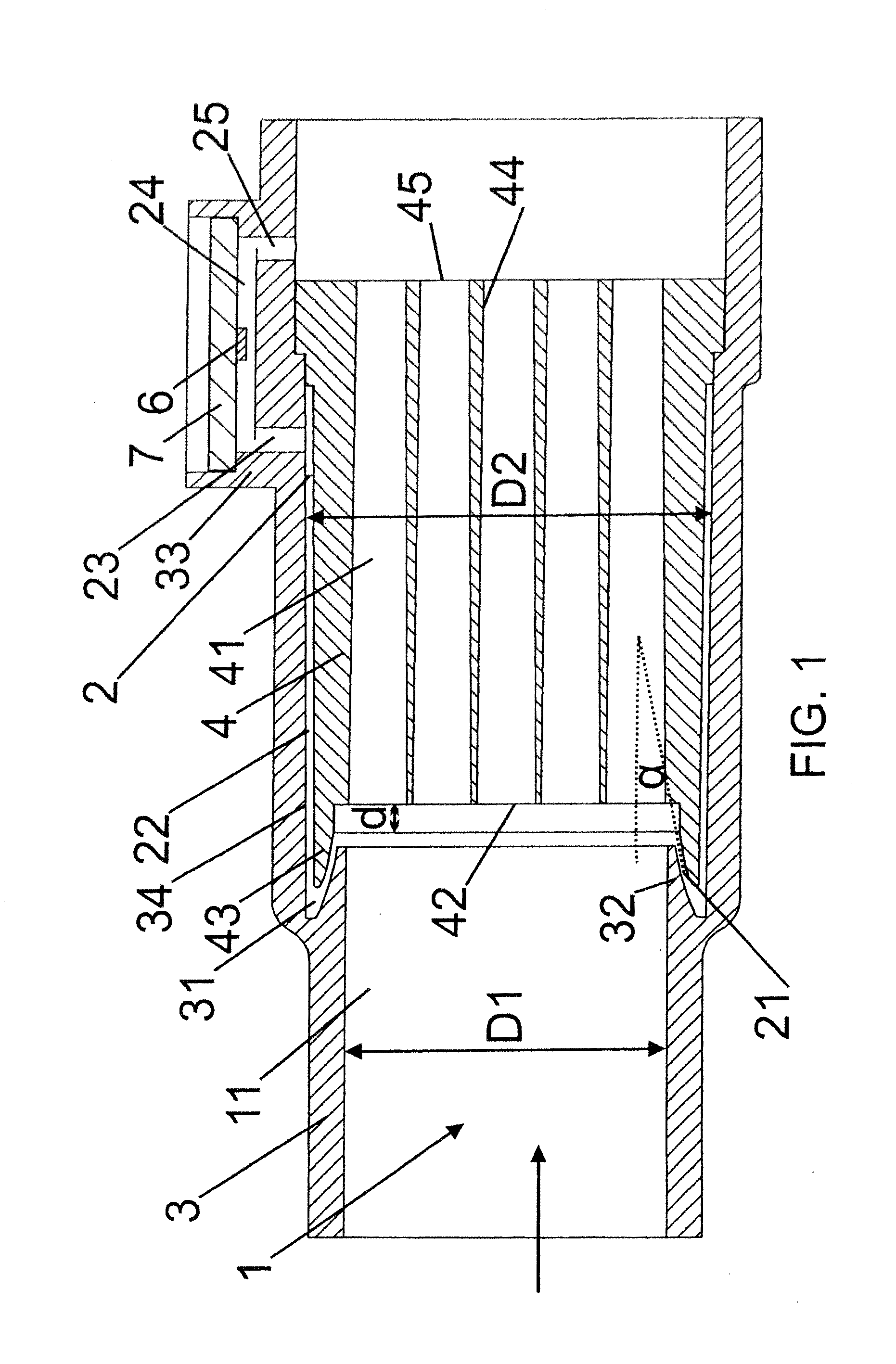
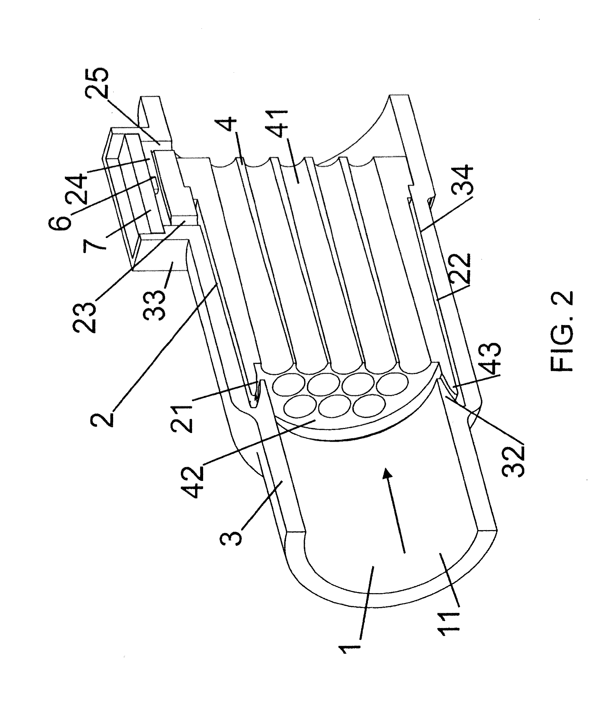
[0014]FIG. 1 illustrates a longitudinal cut of a flow sensor arrangement according to an embodiment of the present invention, and FIG. 2 illustrates a perspective view of such flow sensor arrangement which flow sensor arrangement is longitudinally cut in FIG. 2 for illustration purposes.

[0015]A housing 3 defines a main channel 1 for conveying a fluid. The term “fluid” includes all media capable of flowing along a channel such as gases, liquids, etc. In the present embodiment, the housing 3 basically is of cylindrical shape with a longitudinal aperture of cylindrical shape serving as main channel 1. The fluid to be conveyed in the main channel 1 may flow in a flow direction indicated by an arrow in FIG. 1. The housing 3 may be integral part of a longer tube, or the housing 3 may contribute to a flow sensor arrangement separate from any supply and delivery pipe which pipes may be ...


PUM


Abstract

There is disclosed a flow sensor arrangement, comprising a main channel (1) for conveying a fluid, a bypass (2) connected to the main channel (1) for conveying a portion of the fluid supplied in the main channel (1), and a flow sensor (6) for measuring a flow of the fluid portion in the bypass (2). The bypass (2) branches off from the main channel (1) at an angle (α) of less than 90 degrees between an inlet section (21) of the bypass (2) and a supply section (11) of the main channel (1). By such design means, particles can be prevented from entering the bypass (2) by this adversely affecting the measurements.

Description

TECHNICAL FIELD[0001]The present disclosure refers to a flow sensor arrangement and in particular to a flow sensor arrangement comprising a bypass.BACKGROUND ART[0002]Flow sensors may be used for measuring flows of any fluid such as liquids or gases. Such flow sensors may not be arranged directly in a main channel which main channel conveys the bulk of the fluid. Instead, the flow sensor may be arranged in a bypass bypassing the main channel into which bypass a portion of the fluid is diverted from the main channel. As a result, the flow sensor measures the flow of such portion of fluid in the bypass. The flow in the bypass in turn is a measure of the flow in the main channel which flow in the main channel can be derived by suitable conversion factors from the flow in the bypass. The arrangement of the flow sensor in the bypass may be owed to a better accessibility, e.g. for taking readings from the flow sensor, or for repair and / or exchange purposes, or to a better resolution in th...

Claims


Application Information

Patent Timeline
Patent Type & Authority Applications(United States)
IPC IPC(8): G01F5/00
CPCG01F1/6842G01F15/12G01F5/00
Inventor HORNUNG, MARKMAYER, FELIXKUTTEL, CLAUDIA
Owner SENSIRION AG
Why Eureka
Try Eureka