LED lighting apparatus and dimming method thereof
a lighting apparatus and dimming technology, applied in lighting apparatus, electroluminescent light sources, light sources, etc., can solve the problems of incandescent lamps with short life, large power consumption, and short life of incandescent lamps, and achieve the effect of increasing control means
- Summary
- Abstract
- Description
- Claims
- Application Information
AI Technical Summary
Benefits of technology
Problems solved by technology
Method used
Image
Examples
first exemplary embodiment
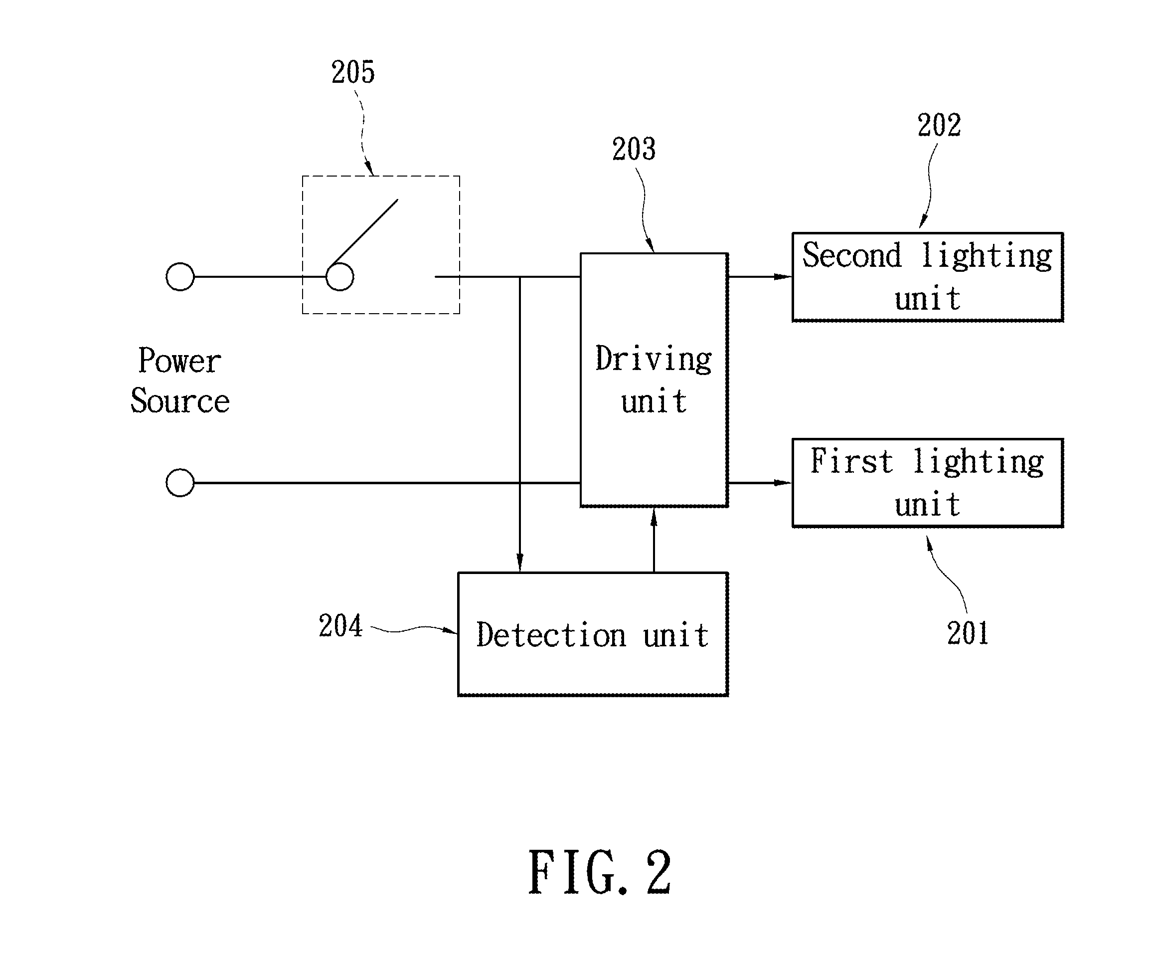
[0040]FIG. 2 shows a circuit diagram of an LED lighting apparatus according to a first exemplary embodiment of the present invention. Please refer to FIG. 2, the LED lighting apparatus includes a first lighting unit 201, a second lighting unit 202, a driving unit 203, and a detection unit 204. For describing the spirit of the present invention, a power switch 205 is shown in the circuit, to represent the typical light switch on the wall in common users' houses. The first lighting unit 201 and the second lighting unit 202 are both implemented by the LEDs. The differences are that the first lighting unit 201 and the second lighting unit 202 use the lighting units emitting different color temperatures. For example, the first lighting unit 201 emits 6000K color temperature (cold color temperature), and the second lighting unit 202 emits 2900K color temperature (warm color temperature).
[0041]The detection unit 204 is used for detecting the status of the power switch 205. When the detecti...
second exemplary embodiment
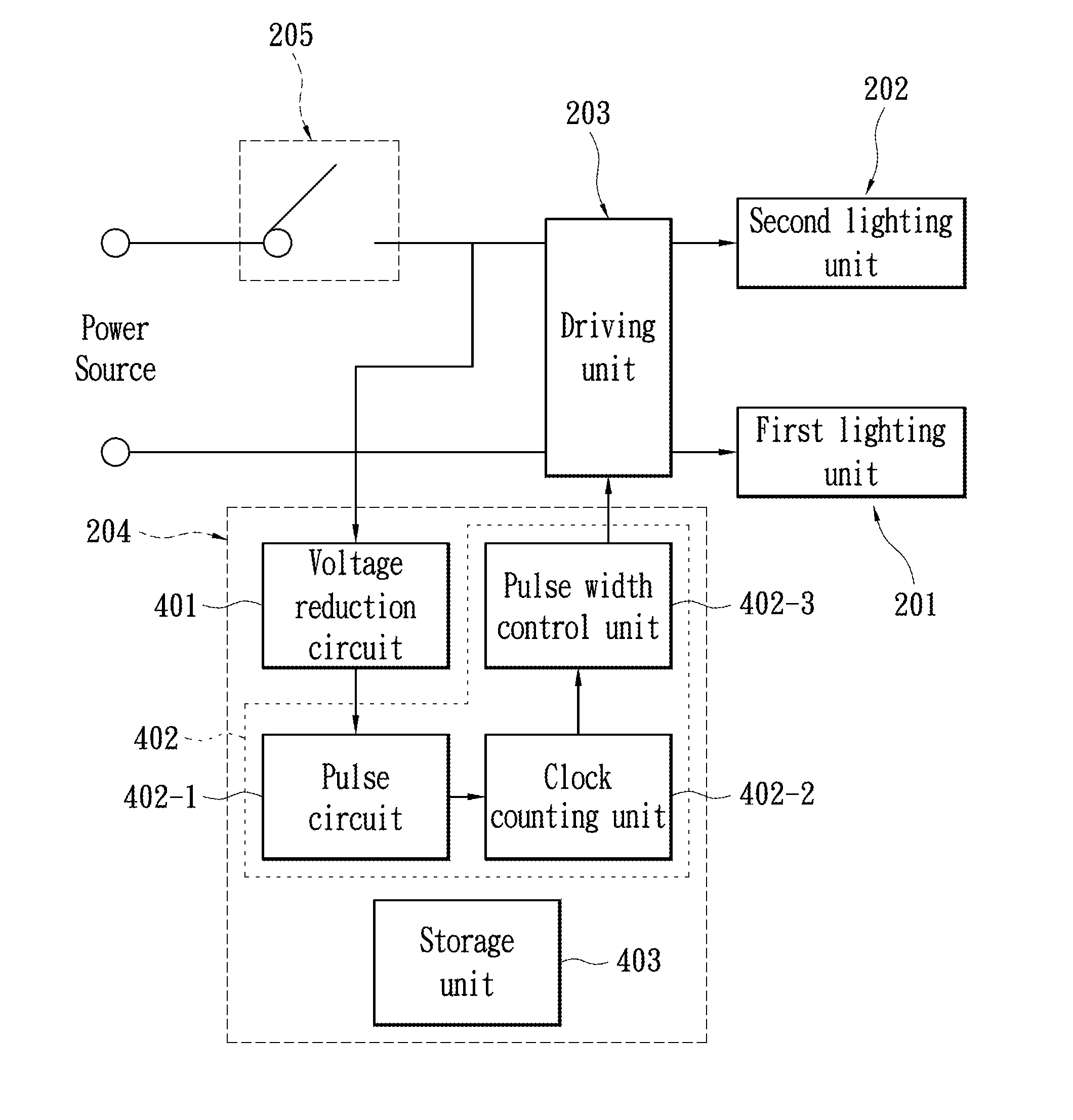
[0045]FIG. 4 shows a relatively detail circuit diagram of an LED lighting apparatus according to a second exemplary embodiment of the present invention. Please refer to FIG. 4, the LED lighting apparatus has the same part as in the first embodiment by having a first lighting unit 201, a second lighting unit 202, a driving unit 203, a detection unit 204, and a power switch 205. The differences are that the detection unit 204 in this exemplary embodiment includes a voltage reduction circuit 401, a control unit 402, and a storage unit 403, wherein the control unit 402 further has a pulse circuit 402-1, a clock counting unit 402-2, and a pulse width control unit 402-3. The voltage reduction circuit 401 is coupled to the power source through the power switch 205. The control unit 402 is coupled to the voltage reduction circuit 401 and the driving unit 203. The control unit 402 counts the time that the power switch 205 has been turned on according to the output voltage of the voltage redu...
third exemplary embodiment
[0051]Similarly, although the aforementioned embodiments only explains method and the circuits for adjusting the color temperature, however, the described method and circuits may also be applied in the application of brightness adjustment. The following description in the third exemplary embodiment describes how the present invention adjusts brightness.
[0052]FIG. 6 shows a circuit block diagram of the LED lighting apparatus according to the third exemplary embodiment of the present invention. Please refer to FIG. 6. The LED lighting apparatus includes a lighting unit 601, a driving unit 602, and a detection unit 603. To explain the spirit of the present invention, the aforementioned circuits further has a power switch 604 representing the lamp switch on the wall in the house of a typical user. The lighting unit 601 is implemented by using LED.
[0053]The detection unit 603 is used for detecting the status of the power switch 604. When the detection unit 603 detects that the power swit...
PUM
 Abstract
Description
Claims
Application Information
 - R&D
- Intellectual Property
- Life Sciences
- Materials
- Tech Scout
- Unparalleled Data Quality
- Higher Quality Content
- 60% Fewer Hallucinations
Browse by: Latest US Patents, China's latest patents, Technical Efficacy Thesaurus, Application Domain, Technology Topic, Popular Technical Reports.
© 2025 PatSnap. All rights reserved.Legal|Privacy policy|Modern Slavery Act Transparency Statement|Sitemap|About US| Contact US: help@patsnap.com


