
Laminated inductor

Active Publication Date: 2013-08-08
TAIYO YUDEN KK
View PDF2 Cites 24 Cited by
  • Summary
  • Abstract
  • Description
  • Claims
  • Application Information

AI Technical Summary

Benefits of technology

The present invention provides a laminated inductor that offers both high inductance and high Q-value. This is achieved by using C-shaped patterns that ensure a relatively large core area and a lower resistance, resulting in a higher Q-value. The use of multiple C-shaped patterns in parallel also helps to achieve higher inductance.

Problems solved by technology

In addition, stack of multiple C-shaped patterns in parallel leads to lower resistance and consequently high Q-value.

Method used


Image

  • Laminated inductor
  • Laminated inductor
  • Laminated inductor

Examples


example

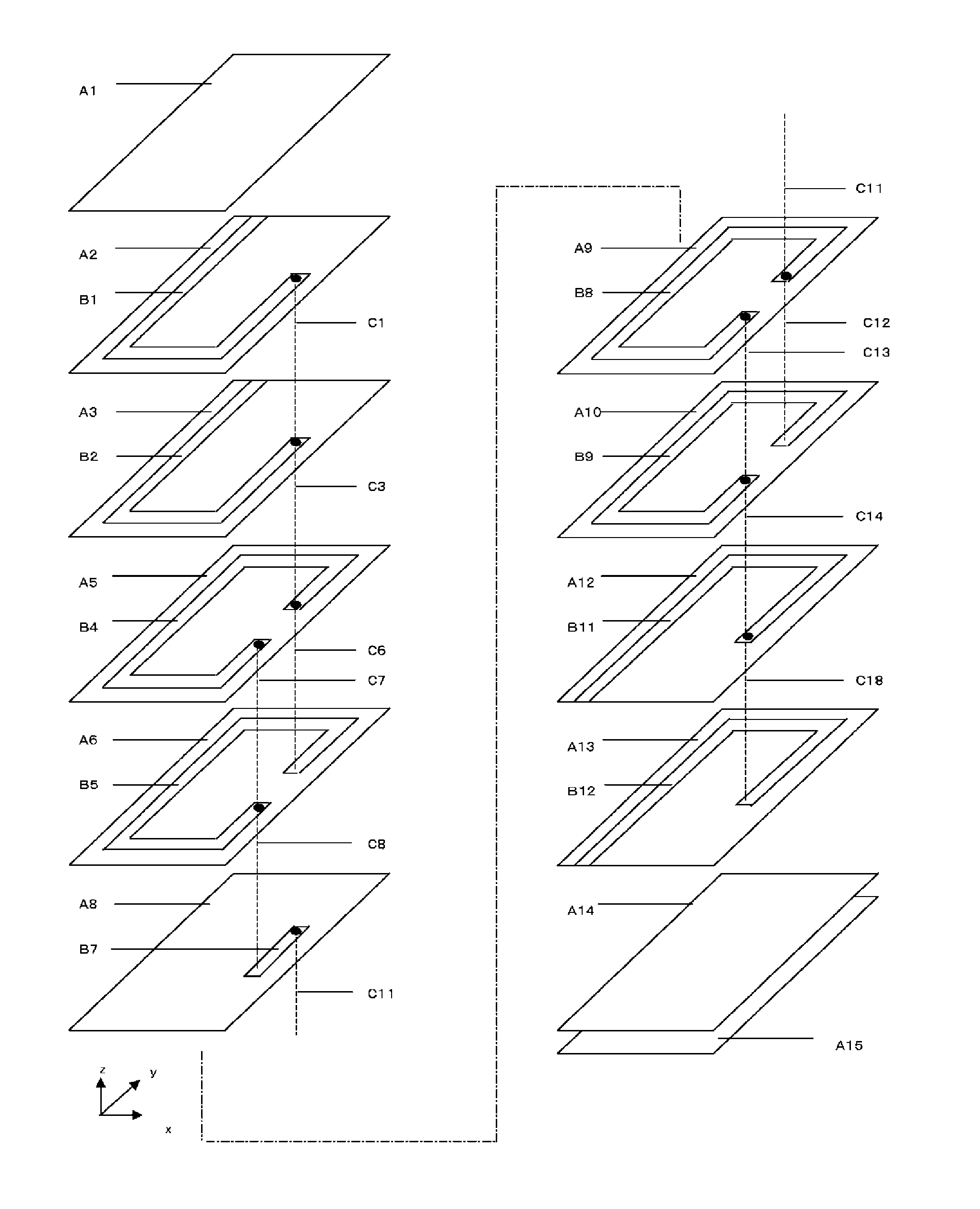
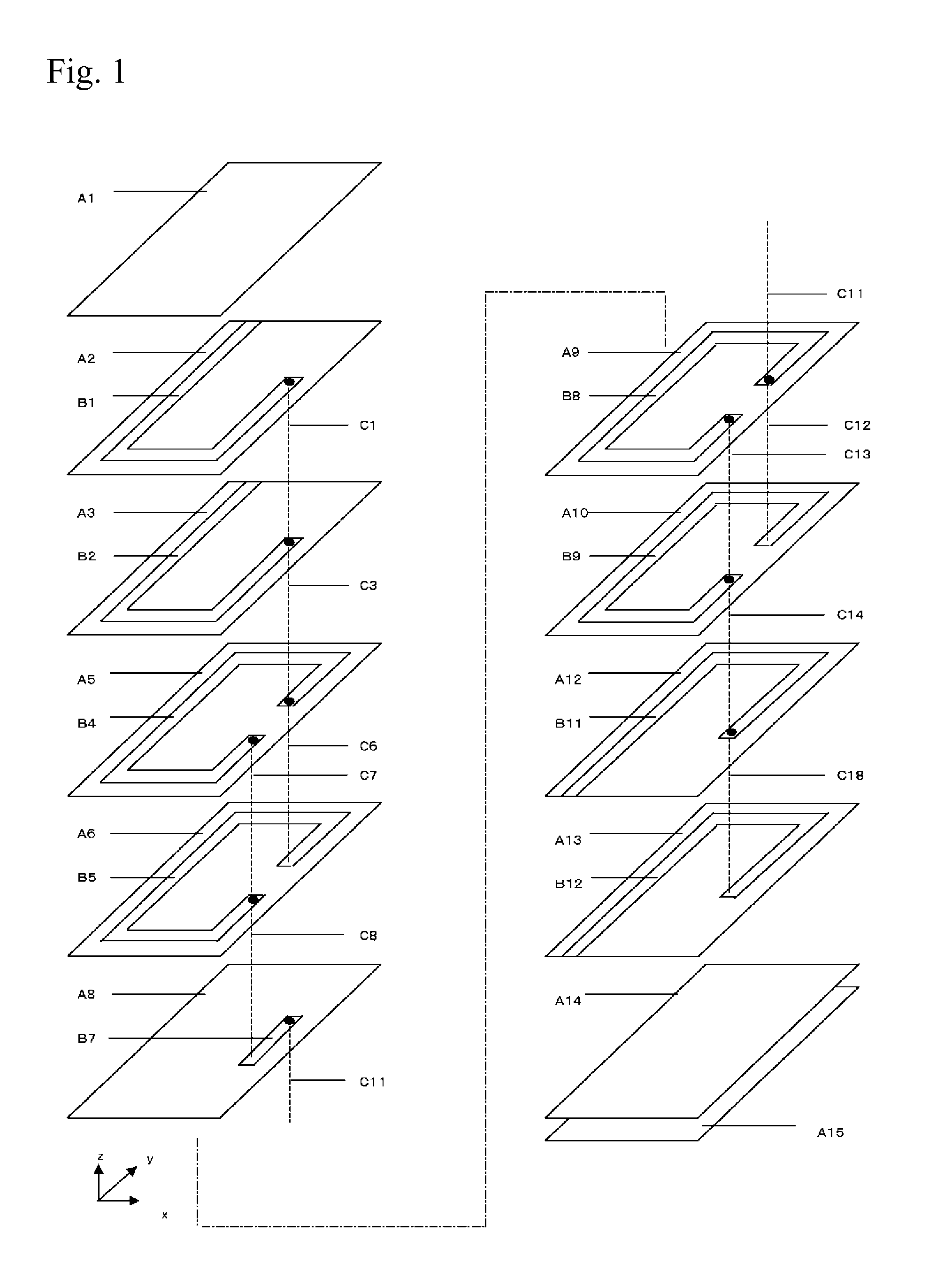
[0047]The results of fabrications and measurements carried out to illustrate the effects of the present invention more clearly, are explained below. To be specific, the laminated inductor of the Example having the structure shown in FIG. 1, and laminated inductor of the Comparative Example having the structure shown in FIG. 6, were manufactured. In the Comparative Example, the structure is such that all conductor patterns are interconnected in parallel in pairs of identically shaped patterns. In the Example, two C-shaped patterns connected in parallel, and one line-shaped pattern connecting the open part of the C-shaped pattern, are connected together to form a single-turn coil. Under both the Example and Comparative Example, laminated inductors were formed with one of three different circumferences (total lengths of the four sides of roughly rectangular shapes) of 1.06 mm, 1.00 mm and 0.94 mm, and line-shaped pattern length of 0.14 mm. The laminated inductors had a size of 0.6 mm×0...


PUM


Abstract

A laminated inductor includes: a laminate constituted by multiple insulator layers; external electrodes formed on the outside of the laminate; and a coil conductor formed spirally inside the laminate, wherein the coil conductor has leaders that electrically connect to the external electrodes and a coil body other than the leaders, wherein the coil conductor has conductive patterns formed on the insulator layers, and via hole conductors that penetrate through the insulator layers and electrically connect the multiple conductor patterns, wherein all of the conductor patterns constituting the coil body are either a C-shaped pattern or line-shaped pattern, wherein the coil body has a partial structure where two or more C-shaped pattern layers are stacked together successively, and wherein the number of C-shaped patterns in the coil body is greater than that of line-shaped patterns.

Description

BACKGROUND[0001]1. Field of the Invention[0002]The present invention relates to a laminated inductor.[0003]2. Description of the Related Art[0004]As electronic devices become smaller and support multiple bandwidths in recent years, the market is demanding laminated inductors that are smaller, higher in Q, and offering narrower inductance steps and smaller induction deviation. With conventional laminated inductors, the coil is formed by combining multiple conductor patterns obtained from multiple screen masks, or combining multiple conductor patterns obtained by shifting identical screen masks. As the laminated inductor becomes smaller, the core area of its coil decreases and inductance drops, while at the same time the magnetic flux does not pass through as effectively and the inductor's Q-value drops as a result. FIG. 6 is a schematic exploded view of an example of laminated inductor based on prior art, where conductor patterns B21 to B29, B210 to B212 of specified shapes are forme...

Claims


Application Information

Patent Timeline
IPC IPC(8): H01F17/00
CPCH01F27/292H01F17/0013
Inventor YOKOYAMA, ICHIROUSUZUKI, TAISUKETAKI, YASUYUKIOYAMA, KAZUHIKO
Owner TAIYO YUDEN KK
Learn More