

Coil component
- Summary
- Abstract
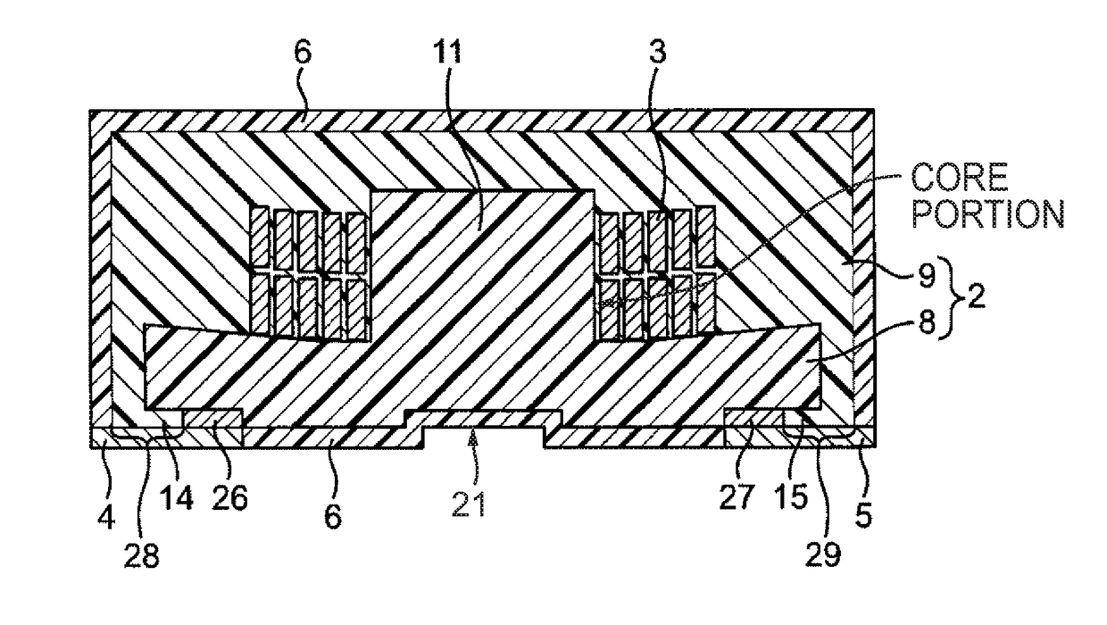
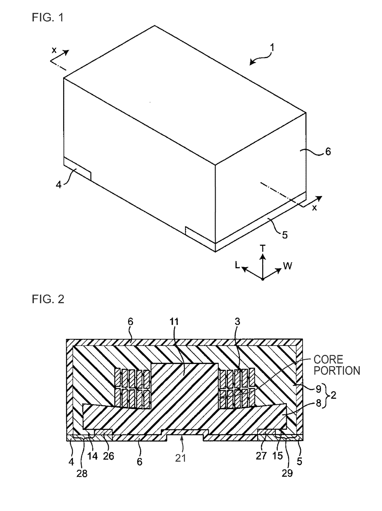
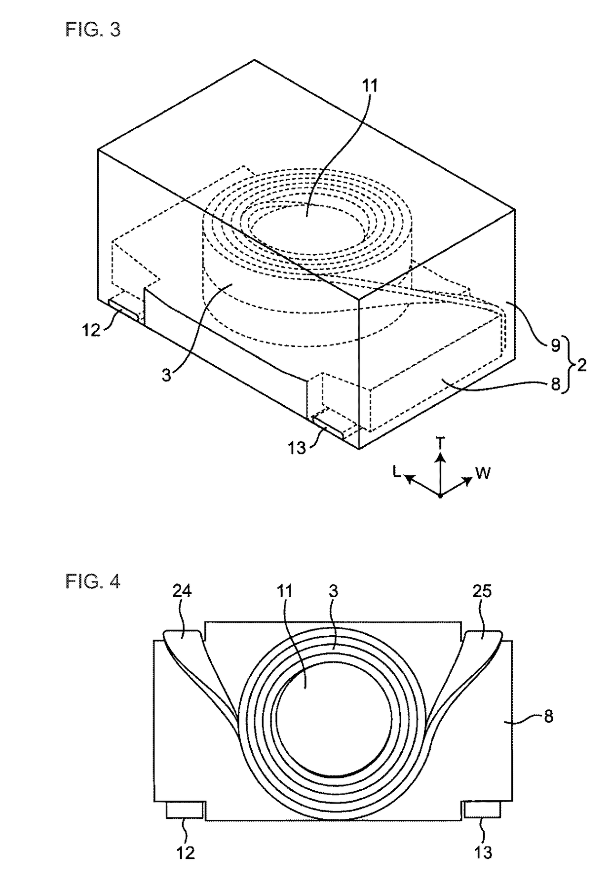
- Description
- Claims
- Application Information
AI Technical Summary
Benefits of technology
Problems solved by technology
Method used
Image

Examples
examples 6 and 7
[0188]Samples (coil components) of examples 6 and 7 were produced in the same manner as example 1 except that the dimensions of the magnetic base were set to be the dimensions shown in Table 4 described below and the dimensions of the rectangular wire and T2−T1 were set to be the dimensions shown in Table 5 described below.
TABLE 4ProtrusionportionDifference indimensionheight betweenRecessed(mm)central portionGrooveportionMajorExternal shapeand end portiondimensiondimensionaxis / Exampledimension (mm)(mm)(mm)(mm)minorNo.LengthWidthHeightt2 − t1WidthDepthWidthDepthaxisHeight61.690.810.590.160.300.060.480.030.86 / 0.400.5171.200.810.490.100.200.010.280.020.61 / 0.340.51
TABLE 5Difference in heightRectangular wire dimensionbetween inner side(mm)and outer side ofExampleRatio ofwinding portion (mm)No.WidthThicknessthickness / widthT2 − T160.210.080.3800.0670.160.020.1250.04
[0189]Evaluation
[0190]Evaluation was performed in the same manner as example 1. The results of the external shape dimensions o...
PUM
| Property | Measurement | Unit |
|---|---|---|
| Length | aaaaa | aaaaa |
| Length | aaaaa | aaaaa |
| Length | aaaaa | aaaaa |
Abstract
Description
Claims
Application Information