Touch-sensing systems

a technology of touch sensor and sensor, applied in the field of touch sensor, can solve the problems of large capacitance, easy noise detection, and easy noise detection of capacitance-based touch sensors, and achieve the effect of enhancing user experience and reducing nois

Inactive Publication Date: 2013-08-08
FLEHKSENEHBL LTD
View PDF23 Cites 4 Cited by
  • Summary
  • Abstract
  • Description
  • Claims
  • Application Information

AI Technical Summary

Benefits of technology

[0018]One might imagine that such an approach could result in the touch sensing signal always being disregarded but in practice it has been found that although sometimes the touch sensing may be repeated more than once, multiple repetitive in

Problems solved by technology

However combining a display screen such as an electrophoretic display screen with a capacitance-based touch sensor presents particular problems because the voltage swings involved can easily couple to the grid of electrodes used for touch sensing.
These problems are particularly acute in large screen devices with fine resolution touch sensing, since these involve a touch sensing grid with large numbers of electrodes, which can easily pick up noise.
There are special problems associated with capacitive touch sensing displays as compared with, say, resistive touch sensing, because voltages on the backplane can be induced onto the touch sensing electrodes, which in turn causes a change in voltage on the electrode capacitance which simulates the effect of touch (which makes a smal

Method used


Image

  • Touch-sensing systems
  • Touch-sensing systems
  • Touch-sensing systems

Examples


Embodiment Construction

[0047]A display screen used in a touch-sensitive display embodiment may be electrophoretic. Such a display screen may have pixels each comprising a capsule containing a set of white particles and a set of black particles, the sets respectively charged positively or negatively. In order to display a required image, voltages are applied to layers associated with the capsules to attract or repel the required set of particles in each capsule as desired.

[0048]An embodiment may however use any other type of display screen, for example, colour (e.g., RGB) and / or electrowetting, LCD, LED, plasma or a different type of electrophoretic display. Thus, the particular waveforms applied to pixels in an embodiment may not be specific to an electrophoretic display or to a particular type of electrophoretic display.

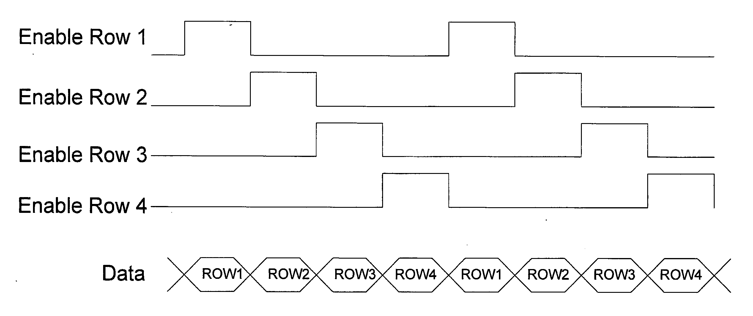
[0049]The embodiment further comprises a projected capacitance touch sensor over the display screen, the sensor comprising a matrix having electrodes, e.g., arranged as rows and columns. ...


PUM


Abstract

A method of projected capacitance touch sensing on a display screen, the method comprising: updating said display screen by applying a drive waveform to each pixel of the display screen over a plurality of frame periods, wherein a said drive waveform for a pixel defines a transition of the pixel from a current pixel state to an updated pixel state over said plurality of frame periods, and wherein said updating comprises selecting each row of said display screen in turn for a row driving period and driving columns of the display screen with a time slice of drive waveforms for pixels of the row to perform a frame update of said display screen, and repeating said frame update to drive pixels of said display with a plurality of successive time slices of said drive waveforms to drive said pixels with said drive waveforms; sensing a signal from a projected capacitance touch sensing electrode of said display screen during a sensing interval, and using said sensing to provide a touch sensing response; identifying when column drive levels of said drive waveforms for pixels of one selected row change by more than a threshold level between said one selected row and a next selected row to provide a column drive row change signal; and inhibiting said touch sensing responsive to said column drive row change signal indicating a greater than said threshold level change of said column drive levels from said one selected row to said next selected row during said sensing interval.

Description

FIELD OF THE INVENTION[0001]This invention generally relates to techniques for employing projected capacitance touch sensing on a display screen, in particular, but not exclusively, on an electrophoretic display screen. Embodiments of the technique are particularly useful for electronic document reading devices. More specifically, the invention relates to a method of projected capacitance touch sensing on a display screen, an electronic device having a display screen in conbination with a projected capacitance touch sensor over said display screen, and touch-sensitive displays.BACKGROUND TO THE INVENTION[0002]Electrophoretic display screens have many advantages for electronic reading devices because they are able to provide a thin and non-volatile display. However combining a display screen such as an electrophoretic display screen with a capacitance-based touch sensor presents particular problems because the voltage swings involved can easily couple to the grid of electrodes used f...

Claims


Application Information

Patent Timeline
IPC IPC(8): G06F3/044
CPCG06F3/0412G06F3/0416G09G3/344G06F3/044G06F3/04166G06F3/0446G02F1/167
Inventor CRONIN, IVANTERRY, NICHOLAS SIMONMOYSE, PHILIPSIMONS, EDWARDFARMER, STEVEN PAUL
Owner FLEHKSENEHBL LTD
Why Eureka
Try Eureka