
Molten salt battery

a technology of molten salt and battery, applied in the field of molten salt batteries, can solve the problems of electric load leveling, natural conditions affect the amount of power generation by natural energy, etc., and achieve the effects of increasing surface area, charging/discharging hour, and reducing capacity density

Active Publication Date: 2013-08-08
SUMITOMO ELECTRIC IND LTD
View PDF7 Cites 18 Cited by
  • Summary
  • Abstract
  • Description
  • Claims
  • Application Information

AI Technical Summary

Benefits of technology

The present invention describes a new design for a molten-salt battery that increases the surface area per unit volume of the electrodes, making it possible to increase the battery capacity without reducing the charging / discharging hour rate. The negative and positive electrodes are alternated, creating a high-capacity and high-energy-density battery.

Problems solved by technology

However, the amount of power generation by natural energy is subject to natural conditions such as climate and weather.
In addition, since it is difficult to adjust the amount of power generation to meet demand, electric-load leveling is needed.

Method used


Image

  • Molten salt battery
  • Molten salt battery
  • Molten salt battery

Examples


first embodiment

[0029]A first embodiment of the present invention will hereinafter be described in detail with reference to FIGS. 1 to 6.

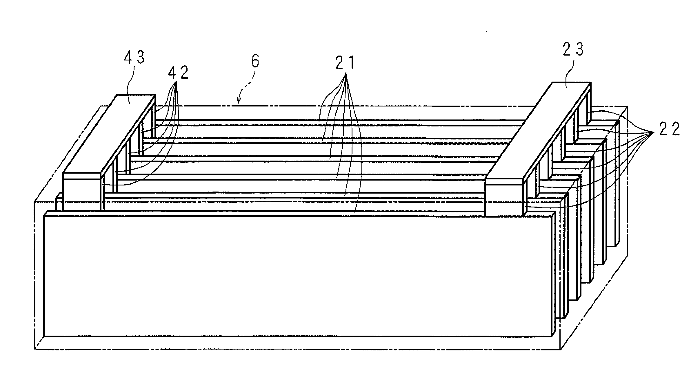
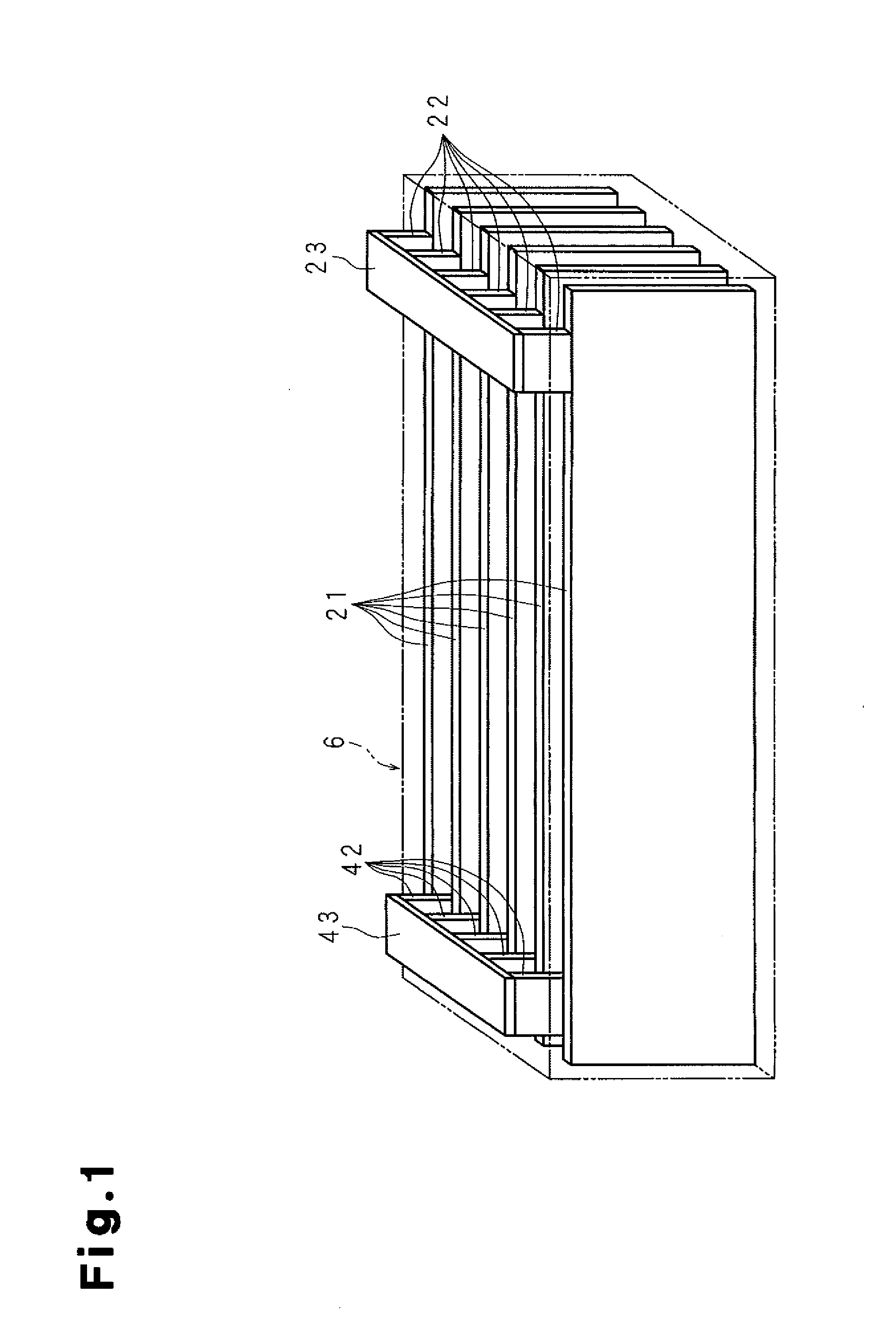
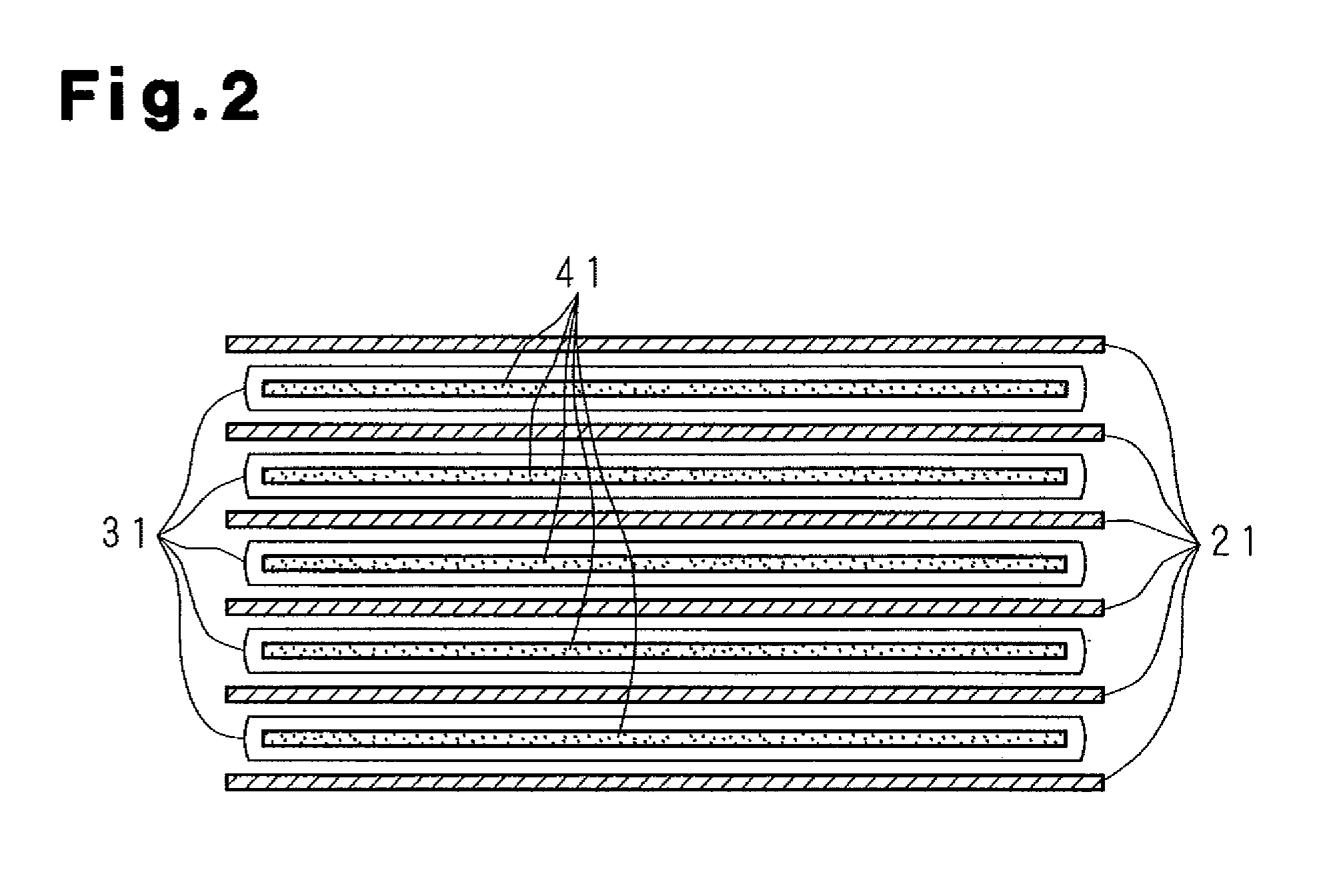
[0030]As shown in FIGS. 1 to 3B, a molten-salt battery according to the first embodiment includes multiple (specifically six) rectangular plate-like negative electrodes 21 and multiple (specifically five) rectangular plate-like positive electrodes 41. Each positive electrode 41 is housed in a bag-shaped separator 31. The negative electrodes 21 and the positive electrodes 41 are arranged laterally and alternately in a standing manner. One negative electrode 21, one separator 31, and one positive electrode 41 constitute one electric generation element. That is, in this embodiment, five electric generation elements and one negative electrode 21 are stacked and housed in a rectangular parallelepiped battery container 10.

[0031]The battery container 10 includes a container body 1 having an opening 1E at the top thereof and a rectangular plate-like lid (not shown). The l...

second embodiment

[0057]In the molten-salt battery according to the first embodiment, the positive electrodes 41 and the negative electrodes 21 stacked alternately with a separator 31 therebetween are housed directly in the battery container 10. On the other hand, in the molten-salt battery according to the second embodiment, the positive electrodes 41 and / or the negative electrodes 21 are pressed by a wall surface of the battery container 10. In the following description of the second embodiment, components identical to those in the first embodiment are designated by the same reference numerals to omit the detailed descriptions thereof.

[0058]As shown in FIGS. 7A and 7B, an aluminum alloy flat retainer plate 9 is arranged between the negative electrode 21 at the front (in the lowest position in FIG. 7A) and the side wall 1D, and an aluminum alloy corrugated plate spring 8 is arranged between the side wall 1D and the retainer plate 9. The plate spring 8 urges the retainer plate 9 rearward (upward in F...


PUM

PropertyMeasurementUnit
thicknessaaaaaaaaaa
thicknessaaaaaaaaaa
thicknessaaaaaaaaaa

Abstract

A molten-salt battery is provided with rectangular plate-like negative electrodes (21) and rectangular plate-like positive electrodes (41) each housed in a bag-shaped separator (31). The negative electrodes (21) and positive electrodes (41) are arranged laterally and alternately in a standing manner. A lower end of a rectangular tab (22) for collecting current is joined to an upper end of each negative electrode (21) close to a side wall (1A) of a container body (1). The upper ends of the tabs (22) are joined to the lower surface of a rectangular plate-like tab lead (23). A lower end of a rectangular tab (42) for collecting current is joined to an upper end of each positive electrode (41) close to a side wall (1B) of the container body (1). The upper ends of the tabs (42) are joined to the lower surface of a rectangular plate-like tab lead (43).

Description

TECHNICAL FIELD[0001]The present invention relates to a molten-salt battery that uses a molten salt electrolyte and, more particularly, to a molten-salt battery in which a separator containing a molten salt is arranged between a positive electrode and a negative electrode.BACKGROUND ART[0002]Power generation by solar power, wind power, and other natural energy resources, which emits no carbon dioxide, has recently been promoted. However, the amount of power generation by natural energy is subject to natural conditions such as climate and weather. In addition, since it is difficult to adjust the amount of power generation to meet demand, electric-load leveling is needed. Thus leveling generated electric energy through charging and discharging requires a high-energy-density, high-efficiency, and high-capacity storage battery. Molten-salt batteries, which use a molten salt electrolyte to meet such requirements, have been attracting attention.[0003]A molten-salt battery includes an ele...

Claims


Application Information

Patent Timeline
Patent Type & Authority Applications(United States)
IPC IPC(8): H01M2/26H01M2/18H01M10/39H01M4/02H01M4/485H01M50/466H01M50/533H01M50/54
CPCH01M2/18H01M2/263H01M10/0459H01M2/266H01M10/3981H01M10/399H01M2300/0048H01M10/3909Y02E60/10H01M50/54Y02P70/50H01M50/533H01M50/466H01M4/02H01M10/39
Inventor SAKAI, SHOICHIROFUKUNAGA, ATSUSHIYAMAGUCHI, ATSUSHINITTA, KOJIMAJIMA, MASATOSHIINAZAWA, SHINJI
Owner SUMITOMO ELECTRIC IND LTD
Learn More