Wireless strain gauge/flow sensor

a flow sensor and wireless technology, applied in medical devices, intravenous devices, medical devices, etc., can solve the problems of not taking into account, affecting the patient's health, and calculating the flow rate error can be very harmful to the patien

Active Publication Date: 2013-08-08
STMICROELECTRONICS SRL
View PDF41 Cites 85 Cited by
  • Summary
  • Abstract
  • Description
  • Claims
  • Application Information

AI Technical Summary

Benefits of technology

[0007]In one embodiment, a fluid dispensing system includes a control module and a sensor module. The sensor module is placed in direct contact with the fluid, the fluid flow line, or the fluid container. The sensor module is a wireless sensor module and receives power wirelessly from the control module. The sensor module includes a sensor coupled to an integrated circuit die in which is formed an ASIC. The sensor is formed on a plastic or flex substrate in one embodiment. Alternatively the sensor is a MEMS sensor. The MEMS sensor and the ASIC can be formed in a single integrated circuit die or in separate integrated circuit dies coupled together and packaged in a single package. The sensor module includes an RF antenna which receives RF radiation which is then converted into electric energy which powers the controller and the sensor. The sensor can be a strain gauge, a pressure sensor, a flow rate sensor, or any other suitable sensor capable of measuring a desired fluid parameter.
[0008]The control module includes a microcontroller and a transceiver. The transceiver emits radio frequency radiation which is received by the antenna of the sensor module. The transceiver of the control module not only transmits energy via the RF signal, but also data. The sensor module can be placed in contact with a fluid being dispensed. The control module is placed outside of the fluid and outside of a container containing the fluid but in close proximity to the sensor module.

Problems solved by technology

Delivering an incorrect dose can lead to serious injury or even death.
However, such a method for monitoring the flow rate has drawbacks in that it often does not take into account volumetric chamber irregularities, temperature fluctuations, fluid viscosity, atmospheric pressure and back pressure variability.
Any error in calculating the flow rate can be very harmful to the patient.
These flow rate and dose size calculation methods are subject to inherent errors introduced by volumetric chamber irregularities, temperature, fluid viscosity, atmospheric pressure, and back pressure variability.
Additionally, and perhaps most critically, there is the potentially fatal human error of administering the wrong drug.

Method used


Image

  • Wireless strain gauge/flow sensor
  • Wireless strain gauge/flow sensor
  • Wireless strain gauge/flow sensor

Examples


Embodiment Construction

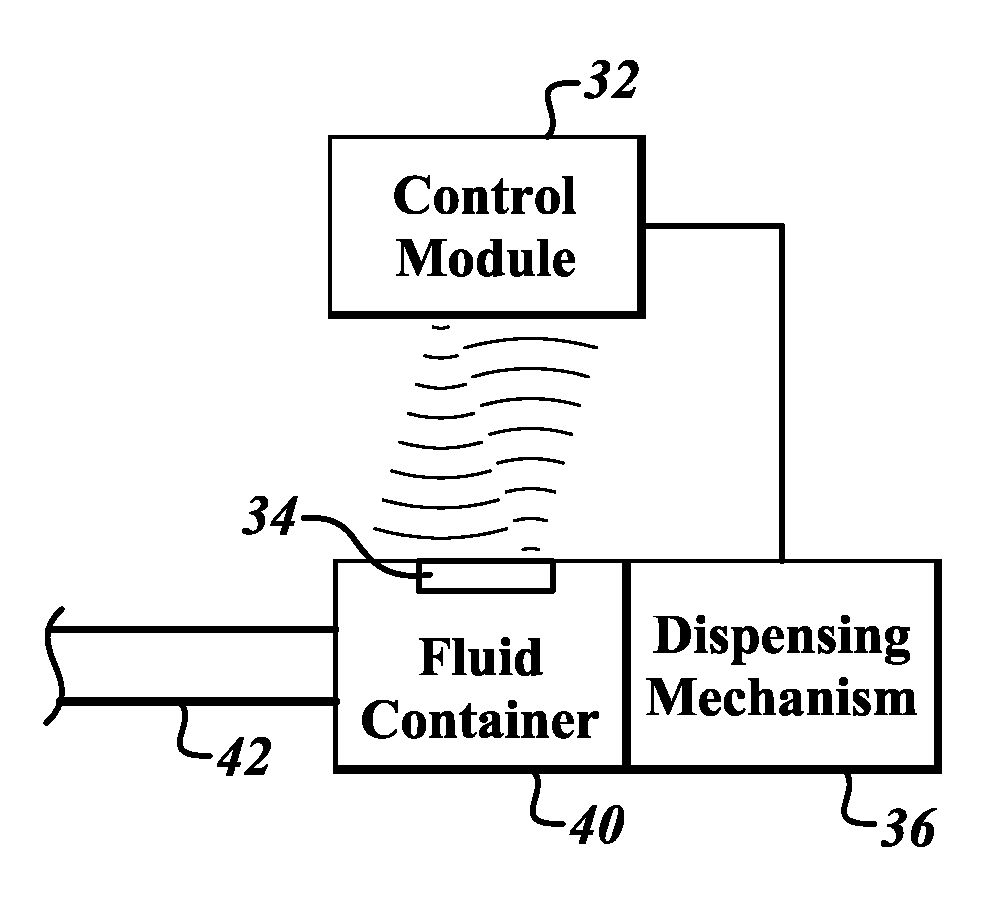
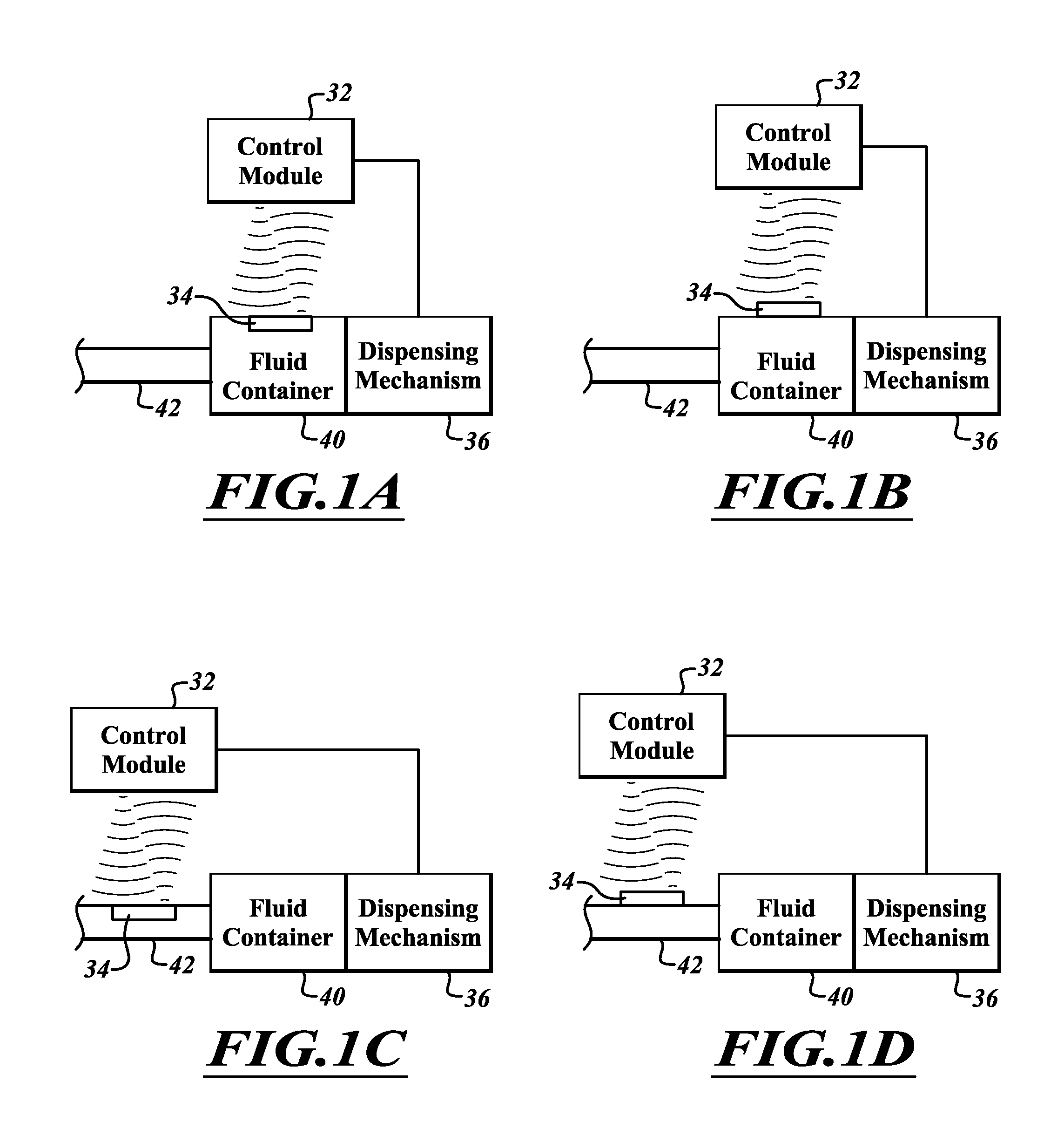
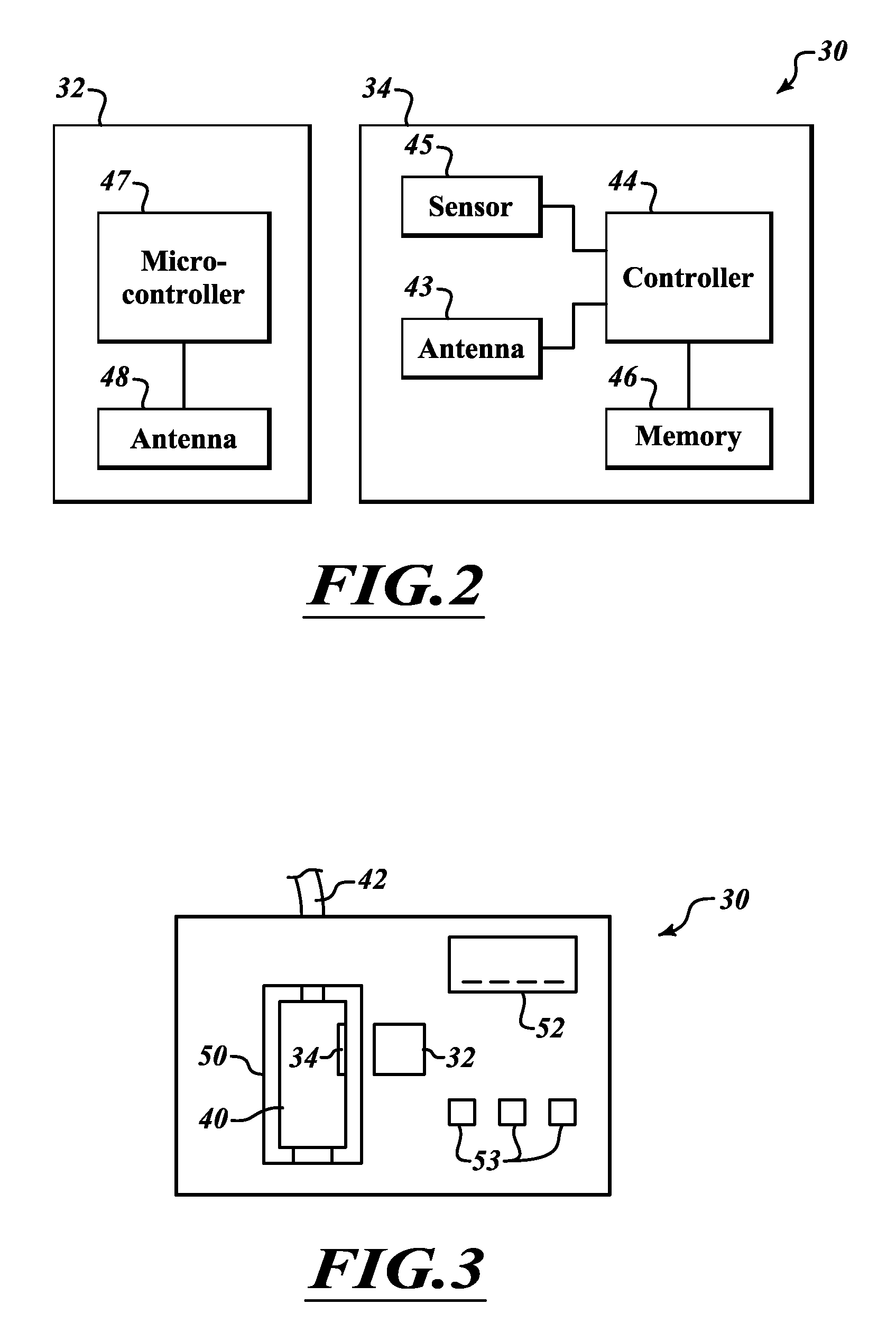
[0032]FIG. 1A is a fluid dispensing system 30 according to one embodiment. The fluid dispensing system 30 includes a control module 32 configured to wirelessly communicate with a sensor module 34. A fluid dispensing mechanism 36 is coupled to the sensor module 32 and to a fluid container 40. The sensor module 34 is coupled inside of the fluid container 40.

[0033]The fluid dispensing mechanism 36 receives a command from the control module 32 to dispense fluid from the fluid container 40 through the fluid line 42 at a particular flow rate. The dispensing mechanism 36 then forces fluid from the fluid container 40 through the fluid line 42. The sensor module 34 is positioned within the fluid container 40 to be able to sense a flow rate of the fluid from the fluid container 40, or to sense a parameter of the fluid from which the flow rate of the fluid can be computed. The sensor module 34 does not receive power from a wired connection or from a battery. Instead, the sensor receives power ...


PUM


Abstract

A flow rate sensor is provided in a wireless, leadless package. The flow rate sensor includes a MEMs sensor coupled to an ASIC and an antenna. The flow rate sensor is powered by radiation received from a control module adjacent the flow rate sensor. The flow rate sensor is placed within a fluid and monitors the flow rate of the fluid. The control module is not in the fluid and receives flow rate data from the flow rate sensor.

Description

CROSS-REFERENCE TO RELATED APPLICATION[0001]This application claims the benefit under 35 U.S.C. §119(e) of U.S. Provisional Patent Application No. 61596631 filed Feb. 8, 2012. This provisional application is incorporated herein by reference in its entirety.BACKGROUND[0002]1. Technical Field[0003]The present disclosure relates to integrated sensor devices. The present disclosure relates more particularly to integrated fluid sensors.[0004]2. Description of the Related Art[0005]Fluid injection systems are utilized in a large variety of applications. Such applications include medical applications, wherein infusion pumps, syringe pumps, auto-injectors, and many other types of devices deliver fluid to a patient. Often, a particular flow rate is desired for delivery of the fluid. For instance, medication or drugs delivered intravenously to a patient during surgery or post-surgery typically are delivered in very precise doses. Delivering an incorrect dose can lead to serious injury or even ...

Claims


Application Information

Patent Timeline
Patent Type & Authority Applications(United States)
IPC IPC(8): A61M5/00
CPCA61M5/1456A61M5/14244A61M5/3134A61M2205/0244A61M2205/0294A61M2205/3317A61M2205/332A61M2205/3334A61M2205/3355A61M2205/3372A61M2205/3569A61M2205/3592A61M2205/50A61M2205/6009A61M2205/8243A61M5/16854A61M5/16877A61M5/172A61M2205/3368
Inventor TROMBLY, NICHOLASFURLAN, PATRICK
Owner STMICROELECTRONICS SRL
Why Eureka
Try Eureka