
Determining an indication of a background level of utility consumption

a utility consumption and background level technology, applied in the direction of electric controllers, instruments, ignition automatic control, etc., can solve the problems of difficult to measure the component of the total level of electricity consumed, the difficulty of nilm systems to identify very small loads, and the small utility consumption of such devices over a short period

Inactive Publication Date: 2013-08-08
SENSUS USA
View PDF10 Cites 13 Cited by
  • Summary
  • Abstract
  • Description
  • Claims
  • Application Information

AI Technical Summary

Benefits of technology

The invention provides a way to measure the level of utility consumption by a group of appliances without needing to monitor each individual appliance separately. This makes the process simpler and easier to install and maintain, while still giving an accurate estimate of the background consumption.

Problems solved by technology

It is challenging for NILM systems to identify very small loads, such as a central heating timer.
Accordingly, the utility consumption by such devices over a short period is small.
However, a typical home or office will generally comprise a large number of such devices, many of which remain operational (or powered up) for substantial times (or even permanently).
For example, where a television and computer are in standby mode, a washing machine is operating a spin cycle, an electric kettle is boiling and an oven clock is performing its usual always-on function, it is not easy to measure which component of the total level of electricity consumed corresponds to a background level of consumption.
Given the large number of appliances in any business or household, it is clear that neither of these approaches provide a practical method of measuring the background level of consumption of a utility.
In particular, neither of these approaches is suitable for determining a background level of consumption at regular intervals and neither of them adapts to changes in the characteristics of an appliances (e.g. as an appliance ages and becomes less efficient).

Method used


Image

  • Determining an indication of a background level of utility consumption
  • Determining an indication of a background level of utility consumption
  • Determining an indication of a background level of utility consumption

Examples


Embodiment Construction

[0039]In the description that follows and in the figures, certain embodiments of the invention are described. However, it will be appreciated that the invention is not limited to the embodiments that are described and that some embodiments may not include all of the features that are described below, it will be evident, however, that various modifications and changes may be made herein without departing from the broader spirit and scope of the invention as set forth in the appended claims.

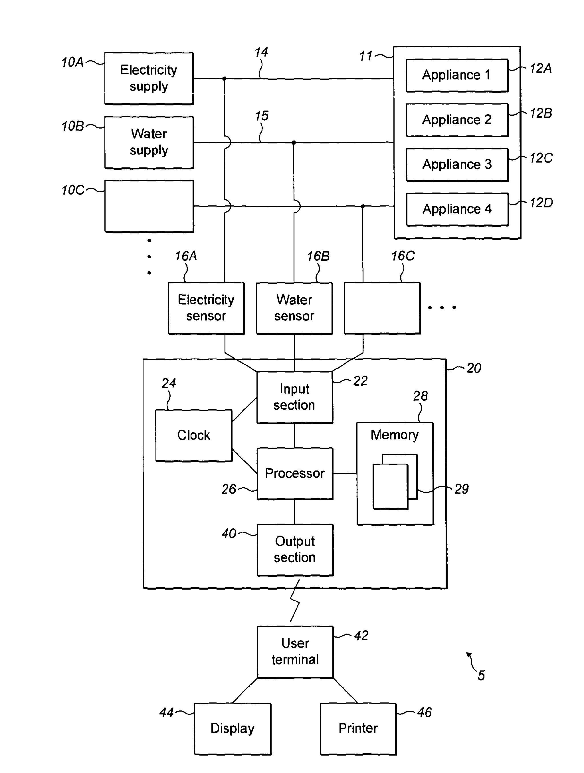
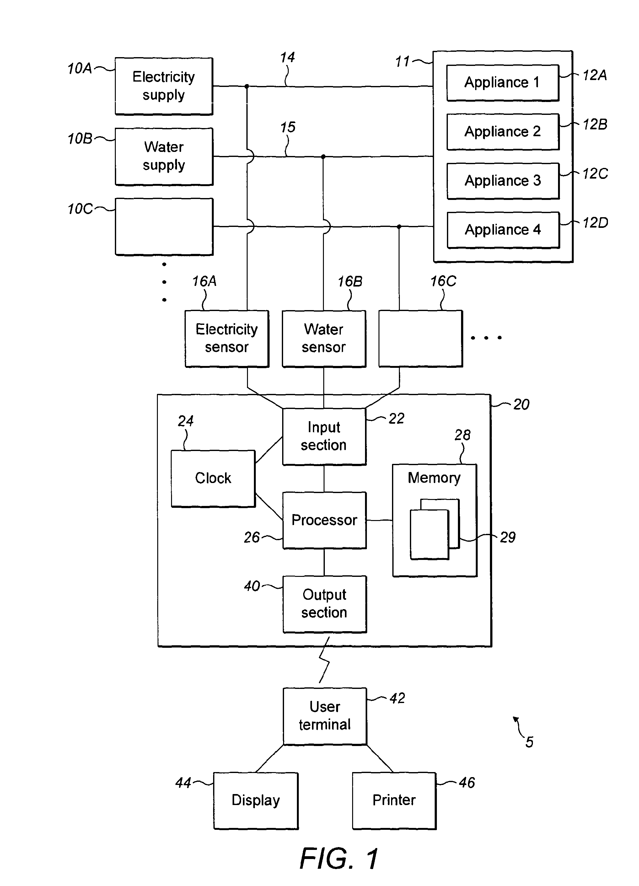
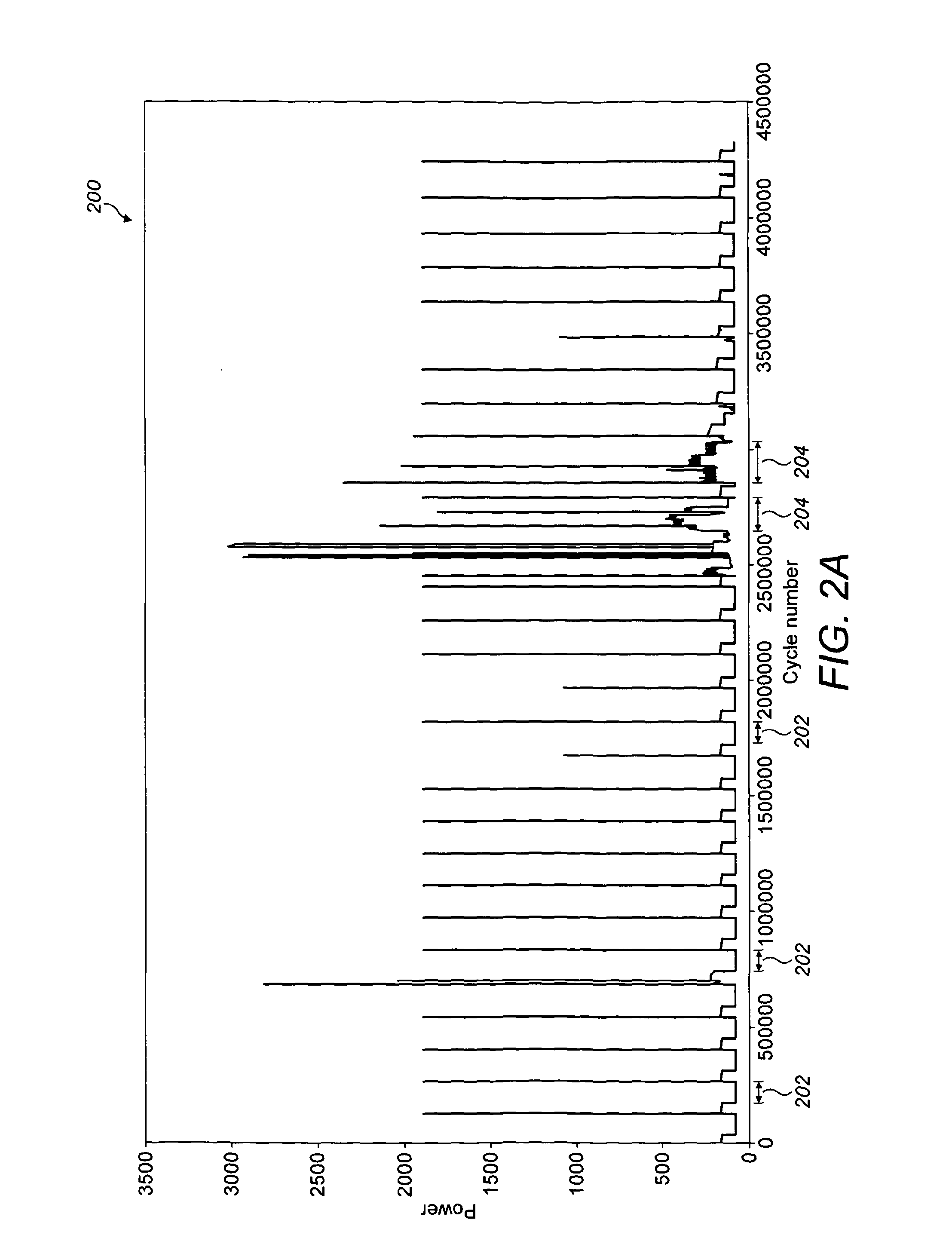
[0040]FIG. 1 schematically illustrates a system 5 according to an embodiment of the invention. The system 5 comprises a site 11, e.g. a house, apartment, office, shop, school, building, factory, etc. One or more appliances (or devices, machines, pieces of equipment) 12A, 12B, 12C, 12D . . . are located at, or form part of, the site 11. The group of appliances 12 may range from any domestic appliances (such as washing machines, refrigerators, hair dryers, etc.) to any industrial or commercial applia...


PUM


Abstract

A non-intrusive method of determining, in respect of a group of appliances that are arranged to consume a utility, an indication of a background level of consumption of the utility by the group of appliances, the method comprising: receiving a series of utility values representative of a total level of consumption of the utility by the group of appliances; determining, based on the received utility values, an indication of a background level of consumption of the utility; and outputting the determined indication of the background level of consumption of the utility.

Description

FIELD OF THE INVENTION[0001]The present invention relates to a method and system for determining, in respect of a group of appliances that are arranged to consume a utility, an indication of a background level of consumption of the utility by the group of appliances.BACKGROUND OF HE INVENTION[0002]For both cost and environmental reasons, consumers (be they individuals, businesses, etc.) are under increasing pressure to reduce the consumption of utilities such as electricity, water and gas.[0003]There have been a number of technology innovations in this area, Devices such as The OWL (http: / / www.theowl.com / index.php?page=about-owl) display the current total electricity consumption of a site (e.g. a home or office) on a local display. Additionally, methods of so-called non-intrusive load monitoring (NILM) have been developed, which involve measuring a level of consumption of a utility by a site and then identifying which particular appliances are consuming the utility at any point in t...

Claims


Application Information

Patent Timeline
IPC IPC(8): G06F17/18G06Q10/06G06Q50/06
CPCG01D4/004G06Q10/06G06Q50/06G06F17/18Y04S20/322Y04S20/38Y02B90/242G01D2204/24G01D21/02G01R21/133Y02B90/20Y04S20/30
Inventor DONALDSON, JAMESSURRALL, SARAHMATTHEWS, ALEXANDERMCCULLOCH, MALCOLM
Owner SENSUS USA
Learn More