Wind Calculation System Using a Constant Bank Angle Turn

a technology of wind calculation and bank angle, applied in the field of aircraft, can solve the problems of not providing as much information as desired about wind, less practicability of using weather balloons over areas, and more expensive and time-consuming use of weather balloons

a technology of wind calculation and bank angle, applied in the field of aircraft, can solve the problems of not providing as much information as desired about wind, less practicability of using weather balloons over areas, and more expensive and time-consuming use of weather balloons

US20130204467A1Active Publication Date: 2013-08-08THE BOEING CO

Image

  • Wind Calculation System Using a Constant Bank Angle Turn
  • Wind Calculation System Using a Constant Bank Angle Turn
  • Wind Calculation System Using a Constant Bank Angle Turn

Examples


Embodiment Construction

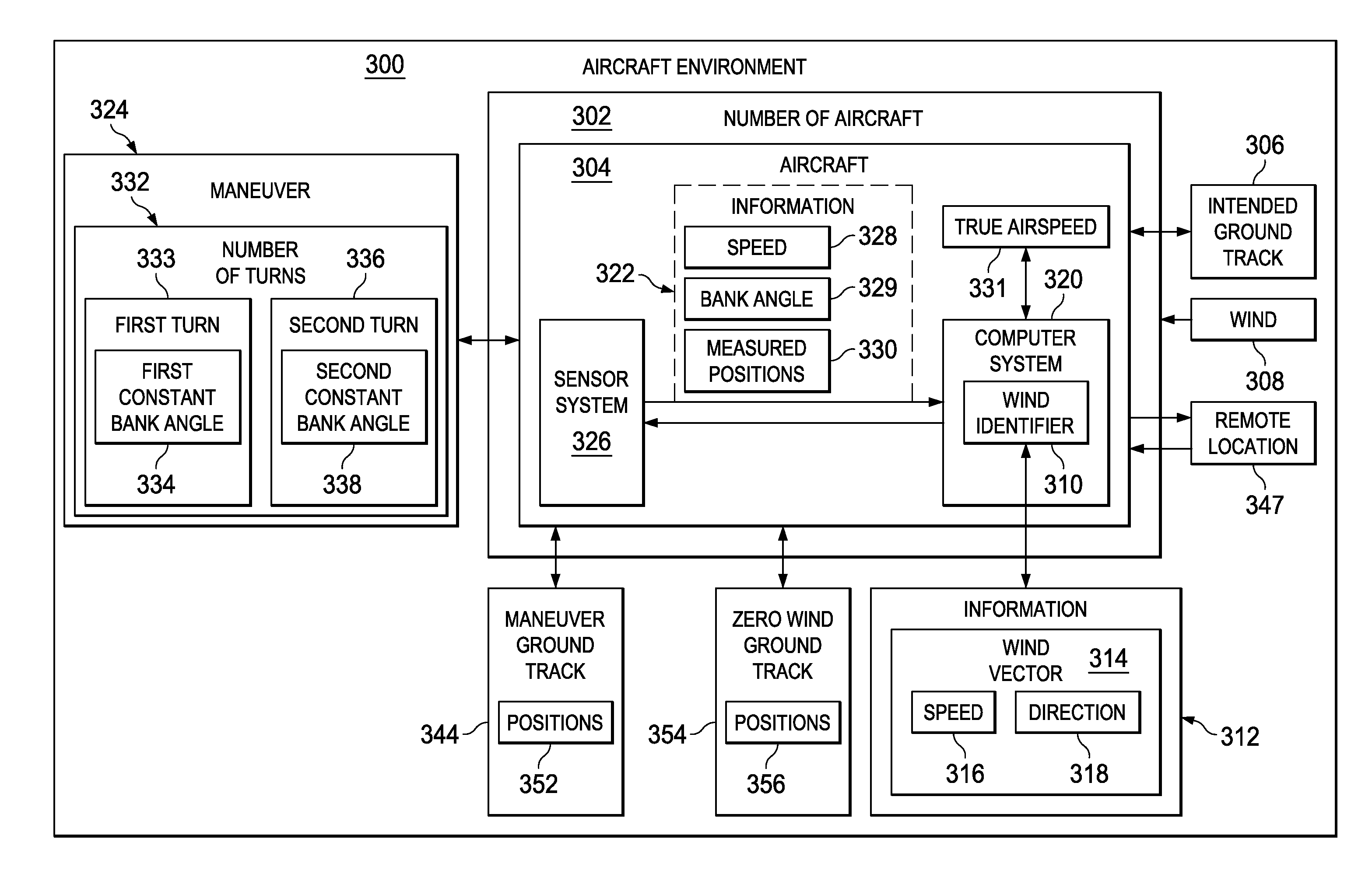
[0023]The illustrative embodiments recognize and take into account one or more different considerations. For example, the different illustrative embodiments recognize and take into account that aircraft without equipment configured to identify a course correction angle taking into account the wind; aircraft, such as unmanned aerial vehicles, may still identify information about the winds that allows the aircraft to be operated in a desired manner.

[0024]The illustrative embodiments recognize and take into account that an aircraft may fly at a constant bank angle turn in circles. The deviation or drift from the center point of each circle flown by the aircraft may be used to identify information about the wind. The illustrative embodiments recognize and take into account that as the number of deviations increase from an intended ground track, such as those from flying circles, the range of an unmanned aerial vehicle may be reduced in a manner making it more difficult to perform missio...


PUM


Abstract

A method and apparatus for operating an aircraft. The aircraft is flown at a constant bank angle in which the aircraft crosses an intended ground track for the aircraft. Information is identified about a wind using positions of the aircraft flying at the constant bank angle.

Description

BACKGROUND INFORMATION[0001]1. Field[0002]The present disclosure relates generally to aircraft and, in particular, to operating unmanned aerial vehicles (UAVs). Still more particularly, the present disclosure relates to the automatic calculation of a heading from an automatically determined wind correction angle by the use of a constant bank angle to reduce repeated course corrections when a cross wind is not accounted for along a flight route.[0003]2. Background[0004]Wind is an environmental factor that may affect the flight of an aircraft. For example, a tailwind is a wind that blows in the direction of travel of the aircraft. A tailwind may increase the relative ground speed of the aircraft and may reduce the total time required to reach a destination. In contrast, a headwind blows against the direction of travel of an aircraft and may have the opposite effect.[0005]Other types of winds also may affect the ground track for the flight of an aircraft. A ground track is the path of ...

Claims


Application Information

Patent Timeline
08 Aug 2013
Publication
US20130204467A1
IPC
G05D1/00
CPC
G08G5/0039; G05D1/0204
Inventors
SPINELLI, CHARLES B.; TAYLOR, BOBBY D.