Two fluid pump

Inactive Publication Date: 2013-08-15
GOJO IND INC
View PDF13 Cites 28 Cited by
  • Summary
  • Abstract
  • Description
  • Claims
  • Application Information

AI Technical Summary

Benefits of technology

[0005]Exemplary embodiments of dispensers include a dispenser housing and a pump system. The pump system includes a housing and a diaphragm. The diaphragm separates the housing into two chambers. The diaphragm has a first position that reduces the volume of the first chamber and expands the volume of the second chamber. In addition, the diaphragm has a second position that exp

Problems solved by technology

In addition, it is sometimes desirable t

Method used


Image

  • Two fluid pump
  • Two fluid pump
  • Two fluid pump

Examples


Example

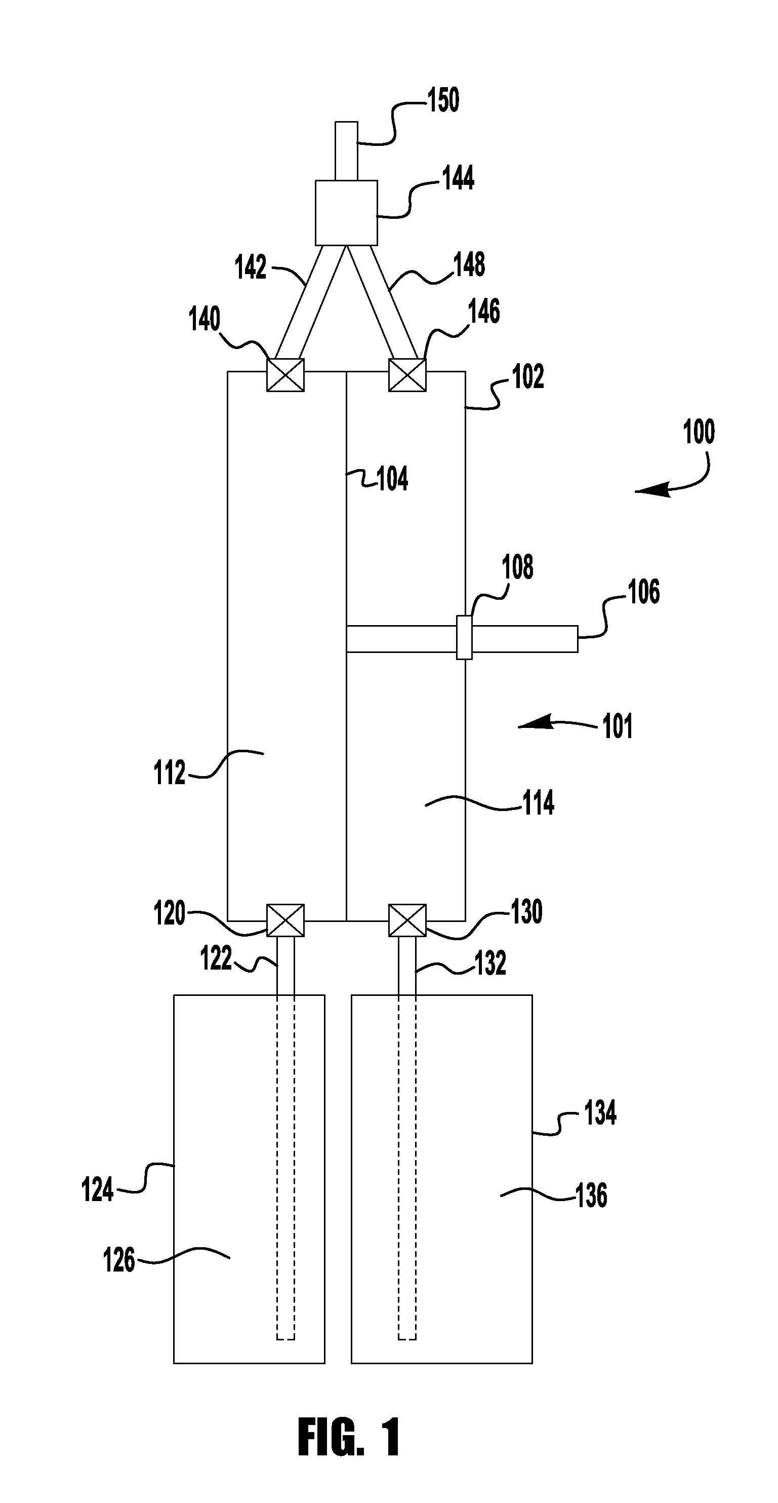
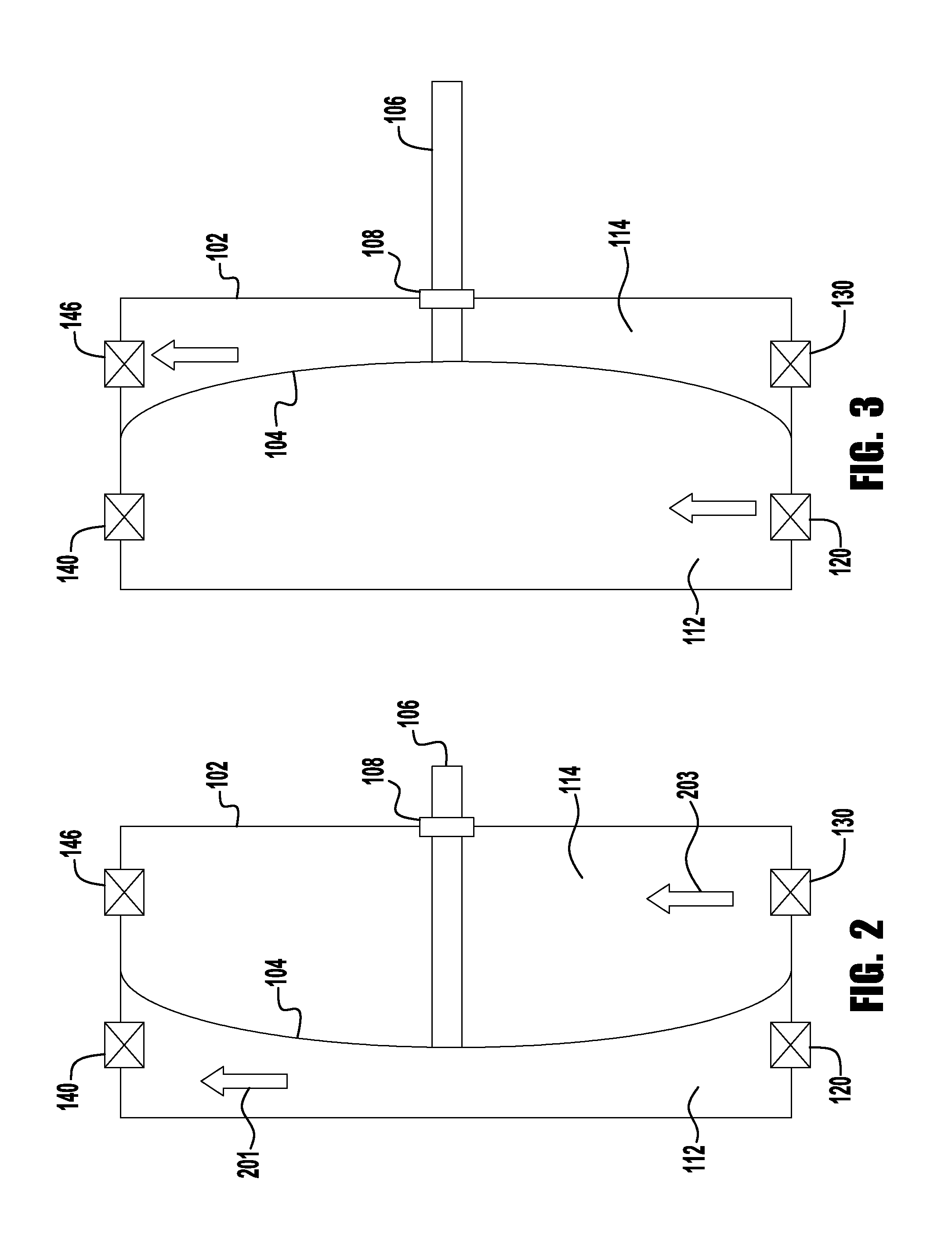
[0014]FIG. 1 illustrates a schematic view of a pumping system 100. Pumping system 100 includes a pump 101. Pump 101 has a housing 102. Housing 102 is divided by diaphragm 104 into a first chamber 112 and a second chamber 114. Diaphragm 104 may be made with any flexible material, such as, for example, a thin elastomeric material, plastic, rubber, or even a thin piece of metal. An actuator, such as, for example, piston 106 is connected to diaphragm 104 and extends through housing 102. A sealing member 108 forms a fluid tight seal between piston 106 and housing 102. The pumping system may be used in a wall-mounted dispenser, a tabletop dispenser or a personal hand held dispenser.

[0015]First chamber 112 has a one-way inlet valve 120 to allow a first fluid into pump 101 and prevents fluid in first chamber 112 from flowing out of first chamber 112. First chamber 112 also includes a one-way outlet valve 140 to allow fluid to flow out of first chamber 112 through tube 142 and into mixing ch...


PUM


Abstract

Pumps with housing and a diaphragms located within the housing are disclosed herein. A diaphragm connected to an actuator separates the housing into a first chamber and a second chamber. Each chamber includes a one-way inlet valve and a one-way outlet valve. Movement of the actuator in a first direction causes the volume of the first chamber to contract and causes the first fluid to be expelled from the first chamber while causing the volume of the second chamber to expand and draw in the second fluid through the second one-way inlet valve. Movement of the actuator in the second direction has the opposite effect causing the first fluid to be drain to the first chamber and the second fluid to be expelled through the second one-way outlet valve. The first and second fluid combine in a mixing chamber and form a foam, which is expelled at an outlet.

Description

RELATED APPLICATION[0001]The present invention claims priority to and the benefits of U.S. Provisional Application Ser. No. 61 / 598,443 titled Two Fluid Pump, which was filed on Feb. 14, 2012, and which is incorporated herein by reference.TECHNICAL FIELD[0002]The present invention relates generally to dispenser systems and a pumping system for dispensing two fluids in the form of a foam.BACKGROUND OF THE INVENTION[0003]Fluid dispenser systems, such as fluid soap and sanitizer dispensers, provide a user with a predetermined amount of fluid upon actuation of the dispenser. In addition, it is sometimes desirable to dispense the fluid in the form of foam. Foam is generally made by injecting air into the fluid to create a foamy mixture of liquid and air bubbles.SUMMARY[0004]Exemplary embodiments of pumps are disclosed herein. In some exemplary embodiments, a pump has a housing and a diaphragm located within the housing. The diaphragm separates the housing into a first chamber and a second...

Claims


Application Information

Patent Timeline
IPC IPC(8): B67D7/70
CPCA47K5/1202A47K5/1215A47K5/16A47K5/14B05B11/3084B65D81/3261B05B9/0413B05B11/1084
Inventor MCNULTY, JOHN J.CIAVARELLA, NICK E.
Owner GOJO IND INC
Why Eureka
Try Eureka