
Simplified Resistance Based Belt Inspection

a technology of resistance and belt inspection, applied in the direction of resistors with plural resistive elements, elevators, instruments, etc., can solve the problems of normal uniform degradation of the support structure, inability to provide continuous monitoring or immediate response to detected fault conditions, and deformation of the support structure strength

Active Publication Date: 2013-08-15
OTIS ELEVATOR CO
View PDF9 Cites 51 Cited by
  • Summary
  • Abstract
  • Description
  • Claims
  • Application Information

AI Technical Summary

Benefits of technology

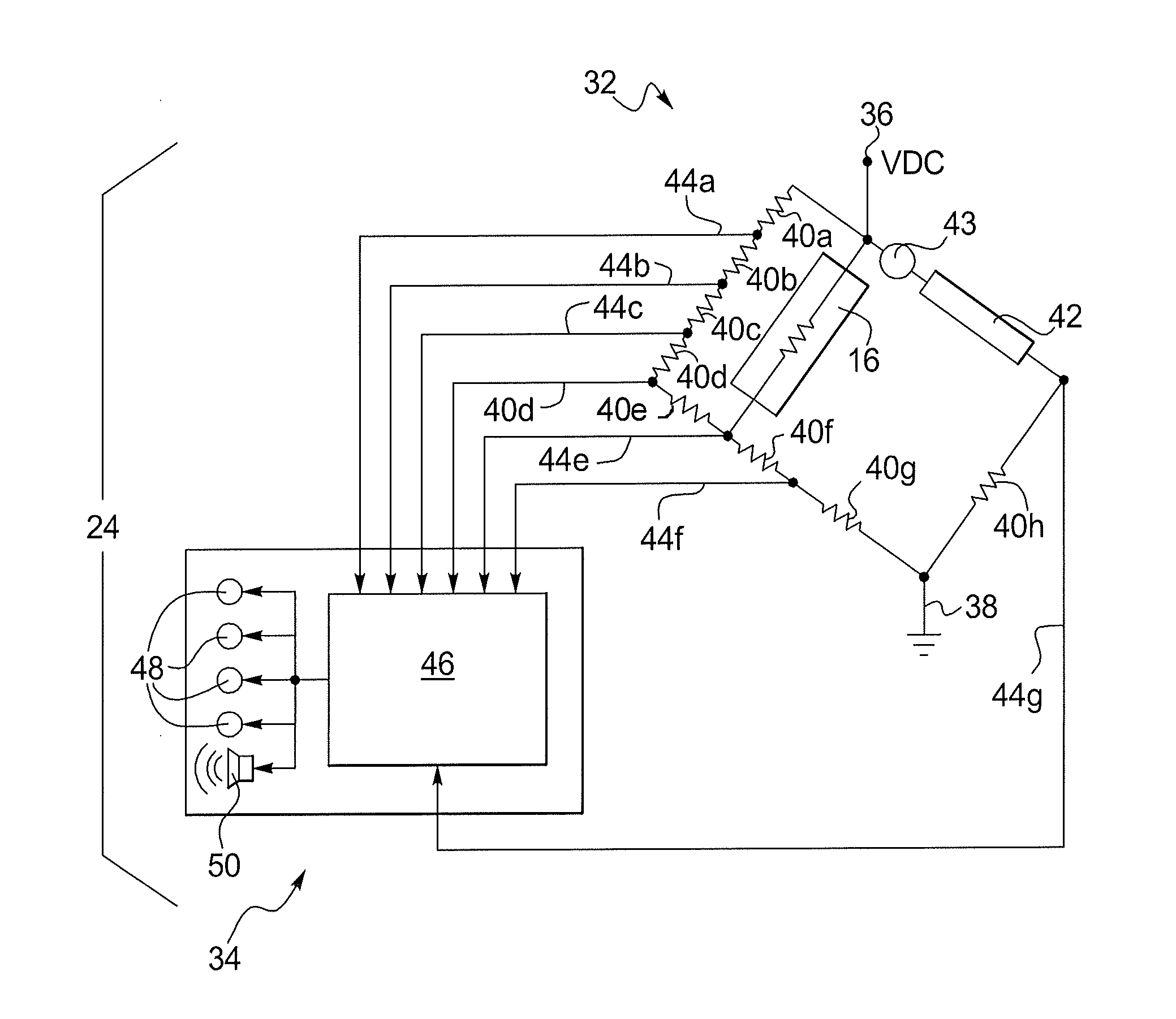
The disclosed resistance circuit and monitoring system use a combination of resistors to monitor the effectiveness of a support structure. The system includes a resistance circuit with two sets of resistors: one on the belt-side and one on the monitor-side. The belt-side resistors include at least one temperature-dependent resistor, while the monitor-side resistors include at least one switched resistor with adjustable resistance. The system also includes an interface circuit with one or more comparators to compare the voltage across the resistors with a reference voltage and generate output signals based on the comparison. The method described in the patent text involves configuring the resistance circuit and performing a series of comparisons to calibrate the monitoring system. The technical effect of the invention is a reliable and accurate way to monitor the effectiveness of a support structure through the use of a resistance circuit with temperature-dependent and switched resistors.

Problems solved by technology

The primary source of the degradation in the strength of the support structure is the cyclic bending of the support structure around sheaves as the elevator is moved up and down in an elevator shaft or hoistway.
The degradation of a support structure is normally not uniform along the length of the support structure, but rather, focused to areas of the support structure that are subjected to high levels or severities of bending cycles.
The digital nature of such systems further rely on sampled data, and thus, are unable to provide continuous monitoring or immediate responses to detected fault conditions.

Method used


Image

  • Simplified Resistance Based Belt Inspection
  • Simplified Resistance Based Belt Inspection
  • Simplified Resistance Based Belt Inspection

Examples


Embodiment Construction

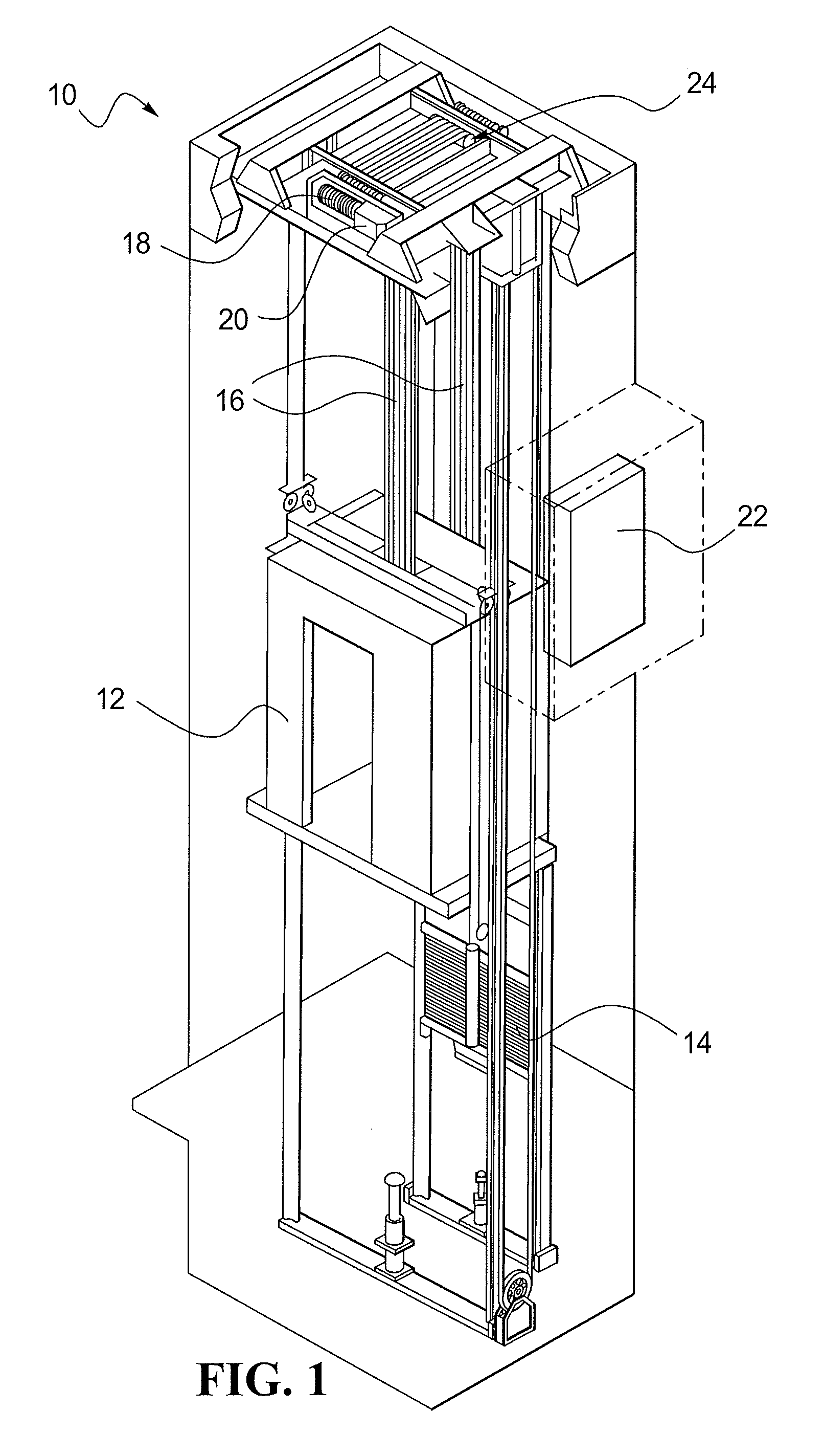
[0026]The present invention relates to monitoring of support structures. While FIG. 1 describes one possible support structure, in particular a tensile support structure, namely belts or ropes used to suspend and / or drive components of an elevator system, the present invention could be used with other support structures. Other exemplary support structures include belts or jacketed cords as used in exercise machines, jacketed cables as used with cranes, or any other multi-strand wire or rope being used in tension. Referring now to FIG. 1, an elevator system 10 is shown in schematic fashion. It is to be understood that the version of the elevator system 10 shown in FIG. 1 is for illustrative purposes only and to present background for the various components of a general elevator system.

[0027]As shown in FIG. 1, the elevator system 10 may include a car 12 coupled to a counterweight 14 by a support structure 16. The support structure 16 may extend over a traction sheave 18 that is drive...


PUM


Abstract

A resistance circuit for monitoring a support structure is provided. The resistance circuit may include a first set of resistors disposed at a belt-side and a second set of resistors disposed at a monitor-side. The first set of resistors may be configured to indicate one or more voltages thereacross corresponding to an effective resistance of the support structure. The first set of resistors may include at least one temperature-dependent resistor. The second set of resistors may be configured to indicate one or more voltages thereacross corresponding to an initial effective resistance of the support structure. The second set of resistors may include at least one switched resistor having an adjustable resistance capable of selectively approximating the initial effective resistance.

Description

CROSS-REFERENCE TO RELATED APPLICATION[0001]This application is a continuation-in-part of PCT International Application No. PCT / US10 / 47445, filed on Sep. 1, 2010.FIELD OF THE DISCLOSURE[0002]The present disclosure generally relates to monitoring systems and methods, and more particularly, to systems and methods for monitoring the condition of a support structure, for example a belt used in an elevator system.BACKGROUND OF THE DISCLOSURE[0003]Tensile support structures, such as coated steel belts or wire ropes containing metal cords, are used to move an elevator car up and down within an elevator shaft or hoistway. Because the condition of the tensile support structure is critical to the safety of the operation of the elevator, there is a need to determine the remaining strength level of the tensile support and detect if the remaining strength level falls below a minimum threshold.[0004]The strength of a tensile support structure can be reduced by normal operation of the elevator ove...

Claims


Application Information

Patent Timeline
IPC IPC(8): G01N27/20G01R35/00H01C1/16
CPCG01N27/20H01C1/16B66B7/1223G01N27/046D07B1/145G01R35/00
Inventor FARGO, RICHARD N.LIASKAS, PETER
Owner OTIS ELEVATOR CO
Learn More