Fixing device and image forming apparatus incorporating same

a technology of fixing device and image forming apparatus, which is applied in the direction of electrographic process apparatus, instruments, optics, etc., can solve the problems of defective fixing, inability to obtain sufficient heat from a heat source, and the temperature of the endless belt to drop significantly

Active Publication Date: 2013-08-15
RICOH KK
View PDF2 Cites 45 Cited by
  • Summary
  • Abstract
  • Description
  • Claims
  • Application Information

AI Technical Summary

Benefits of technology

[0010]Accordingly, the present invention provides a novel fixing device that conveys small and large size sheets and includes a hollow endless rotary body, a pressing member to contact an outer circumferential surface of the endless rotary body, and a nip forming member placed on an inner circumferential side of the endless rotary body to contact the pressing member via the endless rotary body and form a nip thereon. A heating device is placed on the inner circumferential side of the endless rotary body to heat the endless rotary body with radiant heat. A power source is provided to supply power to the heating device. The heating device includes a first heat s

Problems solved by technology

Specifically, when since heat capacity of the endless belt is relatively small, heat transferred to the endless belt is deprived by a sheet, and accordingly the temperature of the endless belt drops significantly in the sheet passage region in the conventional fixing apparatus.
Therefore, when sheets are continuously fed, defective fixing occurs unless the sheet passage region on the endless belt is heated by the heat source up to a prescribed fixing temperature capable of maintaining an appropriate fixing condition.
Further, in a fixing device installed in an image forming apparatus that is capable of feeding relatively small- and large-sized sheets and obtaining higher productivity of the small-sized sheet, an endless belt more likely loses and cannot obtain sufficient h

Method used


Image

  • Fixing device and image forming apparatus incorporating same
  • Fixing device and image forming apparatus incorporating same
  • Fixing device and image forming apparatus incorporating same

Examples


Embodiment Construction

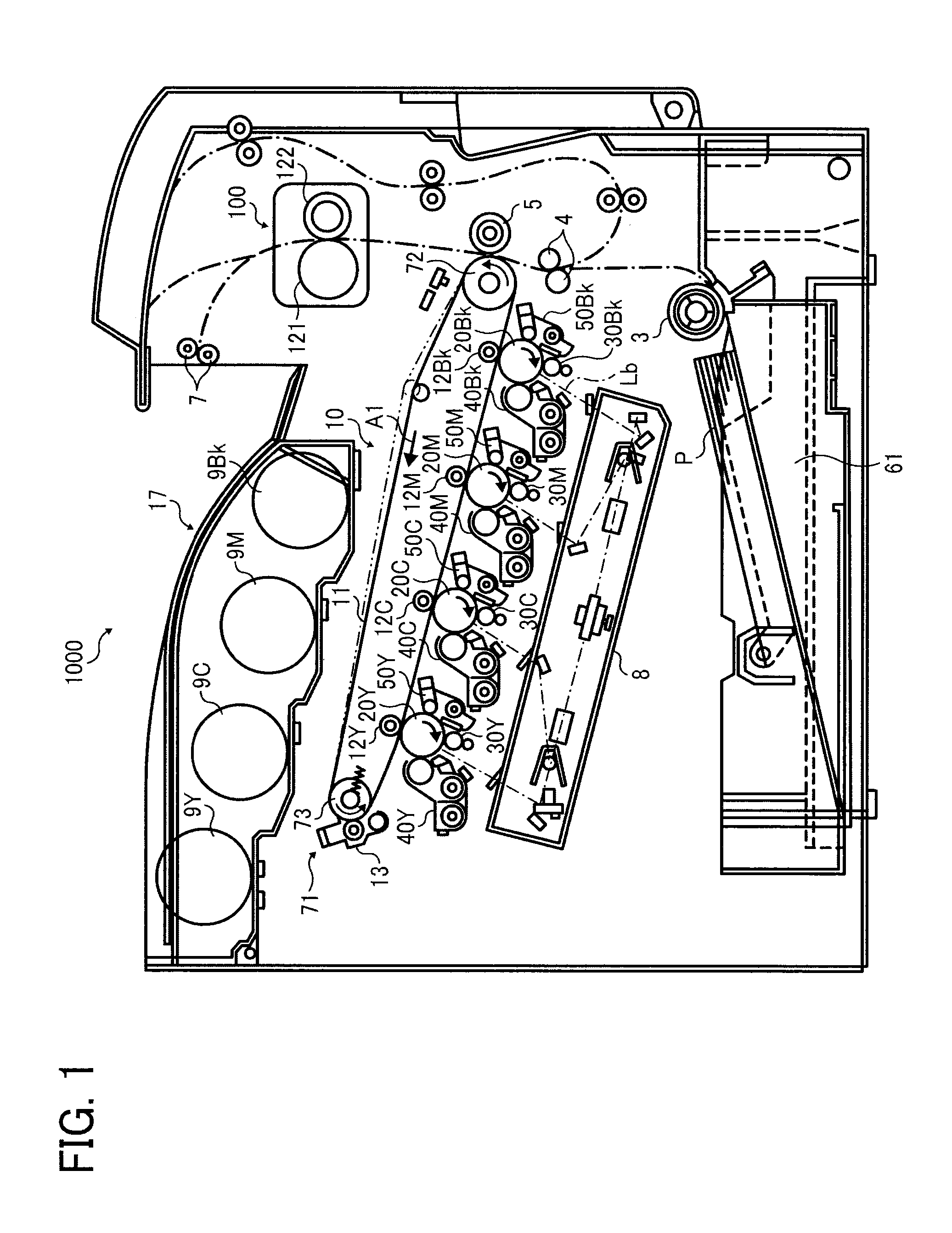
[0026]Referring now to the drawings, wherein like reference numerals designate identical or corresponding parts throughout the several views thereof and in particular to FIG. 1, an overall configuration of an image forming apparatus according to one embodiment of the present invention is initially described. The image forming apparatus shown in FIG. 1 is a color laser printer of a tandem type and is provided with an image station at a center of its body, which consists of four image formation units to form multiple color images. The multiple image formation units are arranged side by side in a stretching direction of an intermediate transfer belt as an endless belt transfer member (hereinafter referred to as a “transfer belt”). The multiple image forming units have the similar configuration with each other except for accommodated developer colors of yellow (Y), magenta (M), cyan (C), and black (Bk) corresponding to resolution components of a color image, respectively.

[0027]As shown ...


PUM


Abstract

A fixing device includes a heating device to heat an endless rotary body with radiant heat, a power source to supply power to the heating device, a first heat source to heat a region on the endless rotary body corresponding to a width of the small size sheet, and a second heat source to heat regions on the endless rotary body corresponding to both widthwise ends of the large size sheet outside the width of the small size sheet. The power source supplies power only to the first heat source when the small size sheet is printed and to both the first and second heat sources when the large size sheet is printed. The power source supplies more power to the first heat source when the small size sheet is printed than when the large size sheet is printed within a maximum power available to the fixing device.

Description

CROSS-REFERENCE TO RELATED APPLICATION[0001]This patent application is based on and claims priority pursuant to 35 U.S.C. §119 to Japanese Patent Application No. 2012-026635, filed on Feb. 9, 2012, in the Japan Patent Office, the entire disclosure of which is hereby incorporated by reference herein.BACKGROUND OF THE INVENTION[0002]1. Field of the Invention[0003]The present invention relates to a fixing device and an image forming apparatus, such as a copier, a printer, a facsimile machine, a multifunctional device, etc., with the fixing device.[0004]2. Description of the Related Art[0005]As used in various types of image forming apparatuses, a fixing device of a thin fixing belt type consisting of an elastic rubber layer and a metal substrate or the like is known. In such a system, due to the low-heat capacity of the thin fixing belt, the energy needed in heating the fixing belt is significantly reduced and a warm-up time period from when power source is turned on, for example, to w...

Claims


Application Information

Patent Timeline
IPC IPC(8): G03G15/20
CPCG03G15/2042G03G2215/2035G03G15/2039G03G15/2082G03G15/2007G03G15/2078
Inventor SAITO, KAZUYAUCHITANI, TAKESHIHASE, TAKAMASAYUASA, SHUUTAROHFUJIMOTO, IPPEINAMEKATA, SHINICHIYAMASHINA, RYOTASEO, HIROSHIWAIDA, TAKUMI
Owner RICOH KK
Why Eureka
Try Eureka