Fan

a technology of fan and housing, which is applied in the direction of non-positive displacement fluid engines, pump components, piston pumps, etc., can solve the problems of troublesome operation of installing the fan, small housing size, and difficulty in providing a fastening structure for fitting the upper and lower segments to each other, and achieve the effect of reducing the size of the housing

Active Publication Date: 2013-08-15
NIPPON DENSAN CORP
View PDF10 Cites 9 Cited by
  • Summary
  • Abstract
  • Description
  • Claims
  • Application Information

AI Technical Summary

Benefits of technology

[0008]According to the above preferred embodiment of the present invention, the fastening structure arranged to fit the upper and lower housing portions to each other can be easily prov

Problems solved by technology

However, when the housing is constructed of the upper and lower segments which are capable of being detached from each other, it is difficult to provide a fastening structure for fitting the upper and lower segm

Method used


Image

  • Fan
  • Fan
  • Fan

Examples


Embodiment Construction

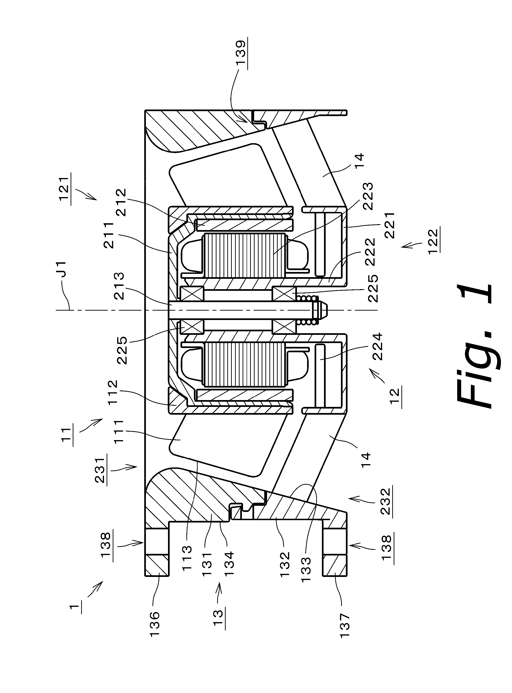
[0025]It is assumed herein that an upper side and a lower side in a direction parallel to a central axis J1 of a fan 1 in FIG. 1 are referred to simply as an upper side and a lower side, respectively. That is, the central axis J1 extends in a vertical direction. Note that the vertical direction and the upper and lower sides as defined above are not meant to indicate positional relationships or directions of members of the fan 1 installed on an actual device. It is also assumed herein that the direction parallel or substantially parallel to the central axis J1 is referred to by the term “axial direction”, “axial”, or “axially”, that radial directions centered on the central axis J1 are simply referred to by the term “radial direction”, “radial”, or “radially”, and that a circumferential direction about the central axis J1 is simply referred to by the term “circumferential direction”, “circumferential”, or “circumferentially”.

[0026]FIG. 1 is a vertical cross-sectional view of a fan 1 ...


PUM


Abstract

In a fan, a housing includes decreased thickness portions and increased thickness portions arranged alternately in a circumferential direction. A distance between a central axis and an edge increases from an air inlet toward an air outlet. An inner circumferential surface has a minimum radius smaller than a distance between the central axis and an outermost portion of the edge. At a boundary between upper and lower housing portions of the housing, the inner circumferential surface has a radius greater than the distance between the central axis and the outermost portion of the edge. The increased thickness portions include component fastening structures defining a fastening structure arranged to fit the upper and lower housing portions to each other.

Description

BACKGROUND OF THE INVENTION[0001]1. Field of the Invention[0002]The present invention relates to a fan arranged to produce an axial air current.[0003]2. Description of the Related Art[0004]A housing of a fan disclosed in FIGS. 9 and 10 of WO 2003 / 075433 has a structure in which two segments thereof are in contact with each other on a lower side of fan blades. The radial thickness of the housing is uniform with respect to an axial direction and a circumferential direction. Both the inside diameter and the outside diameter of the housing gradually increase with decreasing height.[0005]In a casing of a fan disclosed in JP 2003-532026, an inner shell portion is used as a guide surface. The guide surface has the shape of a truncated cone, increasing in diameter with decreasing height, except in an inlet portion thereof. An end edge of each of a plurality of blades extends along the guide surface with a clearance space defined between the end edge and the guide surface. The casing is made...

Claims


Application Information

Patent Timeline
IPC IPC(8): F04D25/08
CPCF04D25/08F04D29/646F04D29/522F04D25/0613
Inventor IWAMOTO, KENJISUGIYAMA, TOMOTSUGUOGUMA, YOSHIAKIKAJI, YASUYUKI
Owner NIPPON DENSAN CORP
Why Eureka
Try Eureka