
Filter device for facilitating characterizing behavior of cells

a filter device and cell technology, applied in cells, diaphragms, immobilised enzymes, etc., can solve the problems of affecting the characterization of cells, changing impedance, and voltage across the electrode, so as to facilitate characterization and enhance the configuration of filter devices.

Active Publication Date: 2013-08-15
APPLIED BIOPHYSICS
View PDF4 Cites 14 Cited by
  • Summary
  • Abstract
  • Description
  • Claims
  • Application Information

AI Technical Summary

Benefits of technology

The patent describes new configurations of filters that can be used to better understand cells that are growing on the filters. These new filters help to make the measurement process faster and more cost-effective.

Problems solved by technology

This small current results in a voltage drop across the small, active electrode of only a few millivolts.
As animal cells attach and spread upon the small, active electrode, they force the current to flow under and between the cells, resulting in changes in impedance, and hence, in the measured voltage across the electrodes.

Method used


Image

  • Filter device for facilitating characterizing behavior of cells
  • Filter device for facilitating characterizing behavior of cells
  • Filter device for facilitating characterizing behavior of cells

Examples


Embodiment Construction

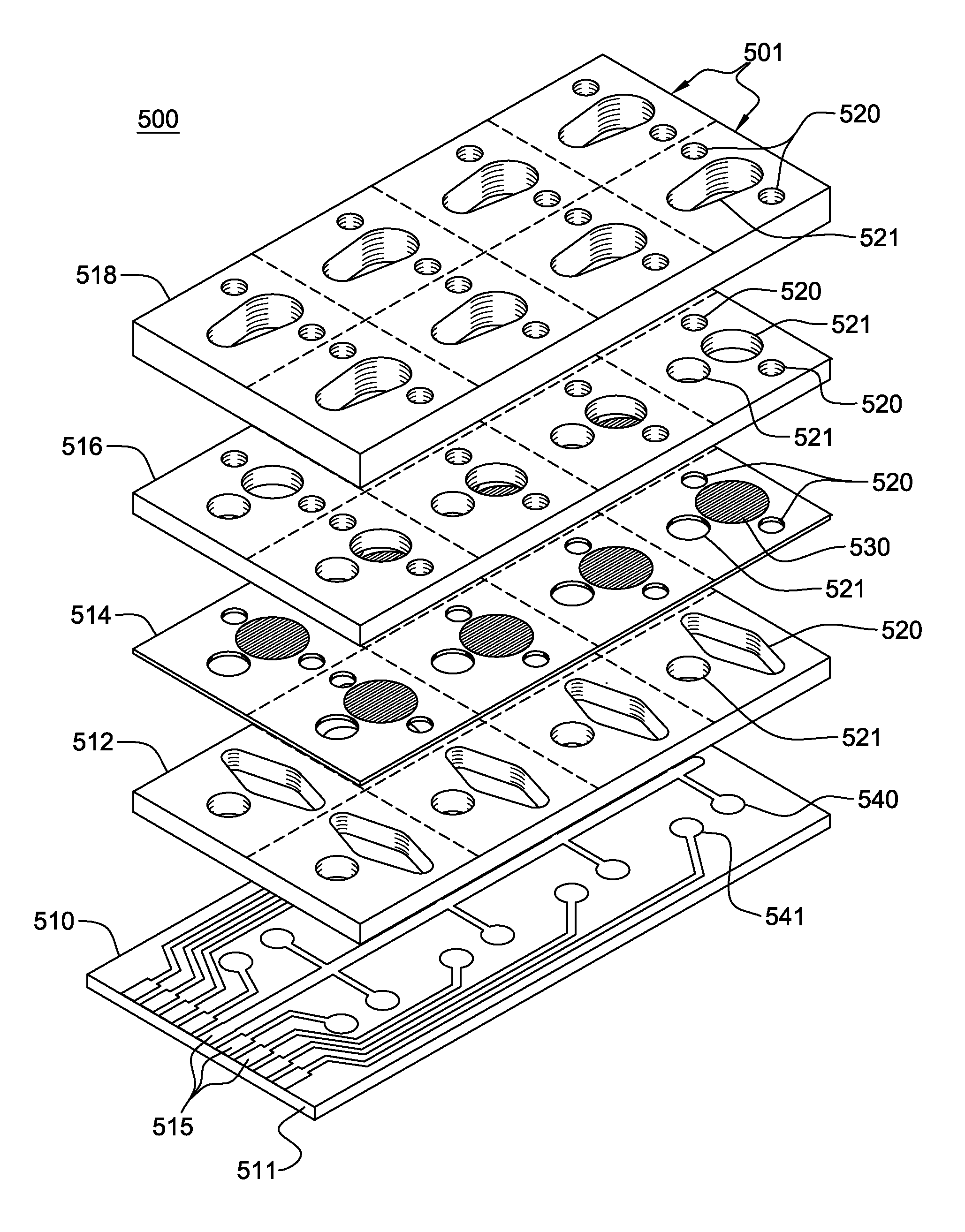
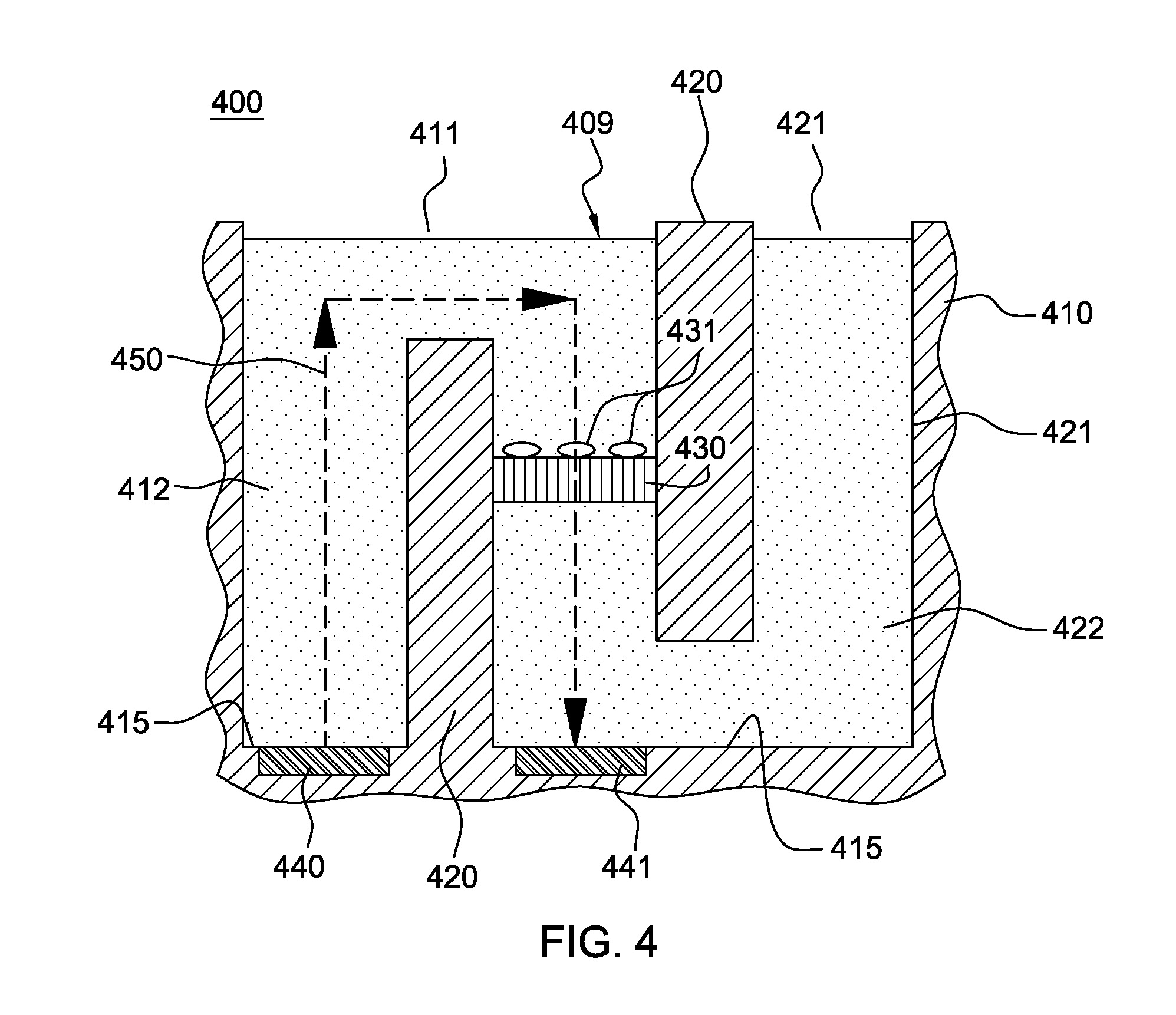
[0021]Reference is made below to the drawings (which are not drawn to scale to facilitate an understanding of the invention), wherein the same reference numbers used throughout different figures designate the same or similar components.

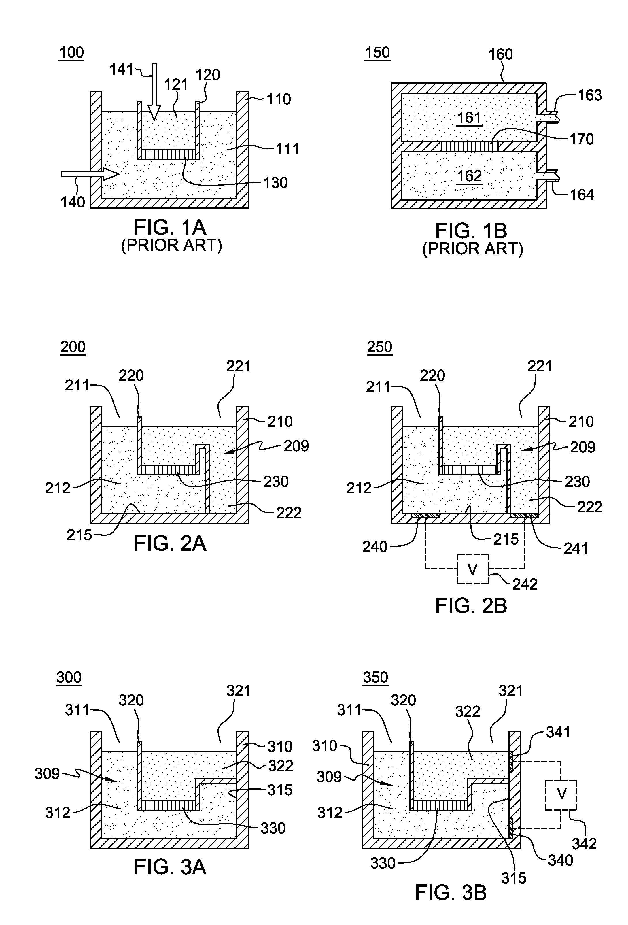
[0022]FIG. 1A depicts one embodiment of a conventional filter device 110 for characterizing, for example, cells introduced onto a filter 130 at the base of an inner well 120 (or filter well insert) suspended within an outer well 110. As shown, a first fluid 111 is disposed in outer well 110 and a second fluid 121 in inner well 120, and outer well 110 and inner well 120 are both open top wells. In operation, inner well 120 with filter 130 may be moved or dipped into the position illustrated in FIG. 1A, within first fluid 111 in outer well 110. If an electrical measurement is to be made across filter 130, then a first electrode 140 is provided at, for example, a side wall or base of outer well 110, and a dipping electrode 141 is inserted into second flu...


PUM

PropertyMeasurementUnit
frequencyaaaaaaaaaa
electrical fieldaaaaaaaaaa
transparentaaaaaaaaaa

Abstract

A filter device is provided which includes a well, at least one top access opening to the well, and a horizontally-disposed filter. The well, which includes an inner surface at least partially defining the well, also includes a first well chamber to accommodate a fluid and a second well chamber to accommodate a fluid. The first well chamber and the second well chamber are separate chambers, and the inner surface at least partially defines the first well chamber and at least partially defines the second well chamber. The at least one top access opening provides independent top access to the first well chamber and the second well chamber, and the horizontally-disposed filter is positioned between and at least partially separates the separate first well chamber and second well chamber of the well.

Description

BACKGROUND[0001]In many applications, filters are employed as substrates to facilitate animal cell growth. By way of example, cells may be grown on a filter support that is held, either vertically or horizontally, between two chambers. Once a cell monolayer is grown upon one side of the filter located between the two chambers, a variety of measurements can be made to characterize the cells, including, permeability of the cell layers, the ability of drugs to pass through the cell layer, the ability of cells to move through the filter, etc. These measurements may be made electrically, with the use of labeled compounds, such as dyes or radioisotopes, or simply by microscopically observing the cells.[0002]One form of measuring cell behavior employs electrical sensing. One example of this is disclosed in U.S. Letters Pat. No. 5,187,096, which is hereby incorporated herein by reference, and referred to herein as the “ECIS® system”. Specifically, the ECIS® system (Electric Cell-substrate I...

Claims


Application Information

Patent Timeline
Patent Type & Authority Applications(United States)
IPC IPC(8): C12M1/12B01L3/00H05K13/00G01N27/28B23P17/04
CPCC12M25/04C12M35/02B01L3/50255Y10T29/494B01L2300/0681B01L2300/0829Y10T29/49002B01L2300/0645C12M41/46
Inventor RENKEN, CHRISTIAN W.
Owner APPLIED BIOPHYSICS
Learn More