
High speed communication jack

a high-speed communication and jack technology, applied in the direction of cross-talk/noise/interference reduction, coupling device connection, printed capacitor incorporation, etc., can solve the problems of signal failure, design of such physical components is plagued by a lack of understanding of what, and still speed limited by the current design of certain physical components

Active Publication Date: 2013-08-15
SENTINEL CONNECTOR SYST
View PDF48 Cites 35 Cited by
  • Summary
  • Abstract
  • Description
  • Claims
  • Application Information

AI Technical Summary

Benefits of technology

The patent text describes a method to adjust the value of a capacitor to prevent reflections of signals from matches traces. This results in a more reliable and accurate signal processing.

Problems solved by technology

However, even as more recent versions of various standards provide for theoretically higher data rates or speeds, they are still speed limited by the current designs of certain physical components.
Unfortunately, the design of such physical components is plagued by a lack of understanding of what is necessary to achieve consistent signal quality at multi-gigahertz and higher frequencies.
If not, a load with one impedance value will reflect or echo part of a signal being carried by a cable with a different impedance level, causing signal failures.
The RJ45 jack is also a significant component in nearly every communications circuit, however, jack manufacturers have not provided the same level of attention to its performance.
Thus, although problems related to existing RJ45 jacks are well documented in tests and their negative impact on high frequency signal lines is understood, the industry seems reluctant to address the issues for this important component of the physical layer.

Method used


Image

  • High speed communication jack
  • High speed communication jack
  • High speed communication jack

Examples


Embodiment Construction

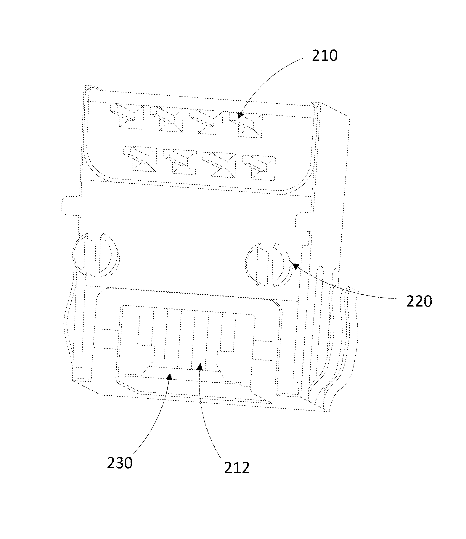
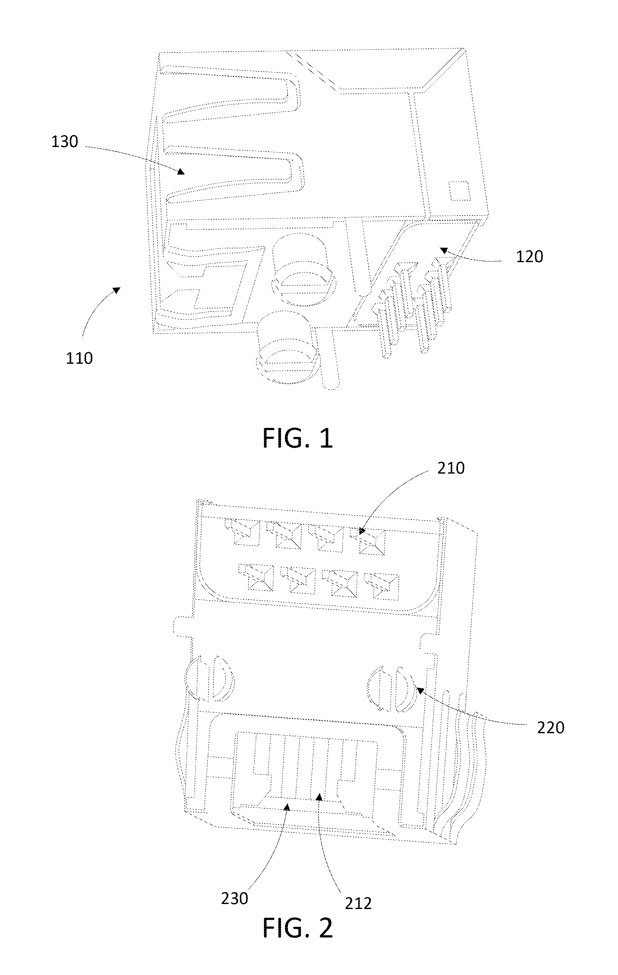
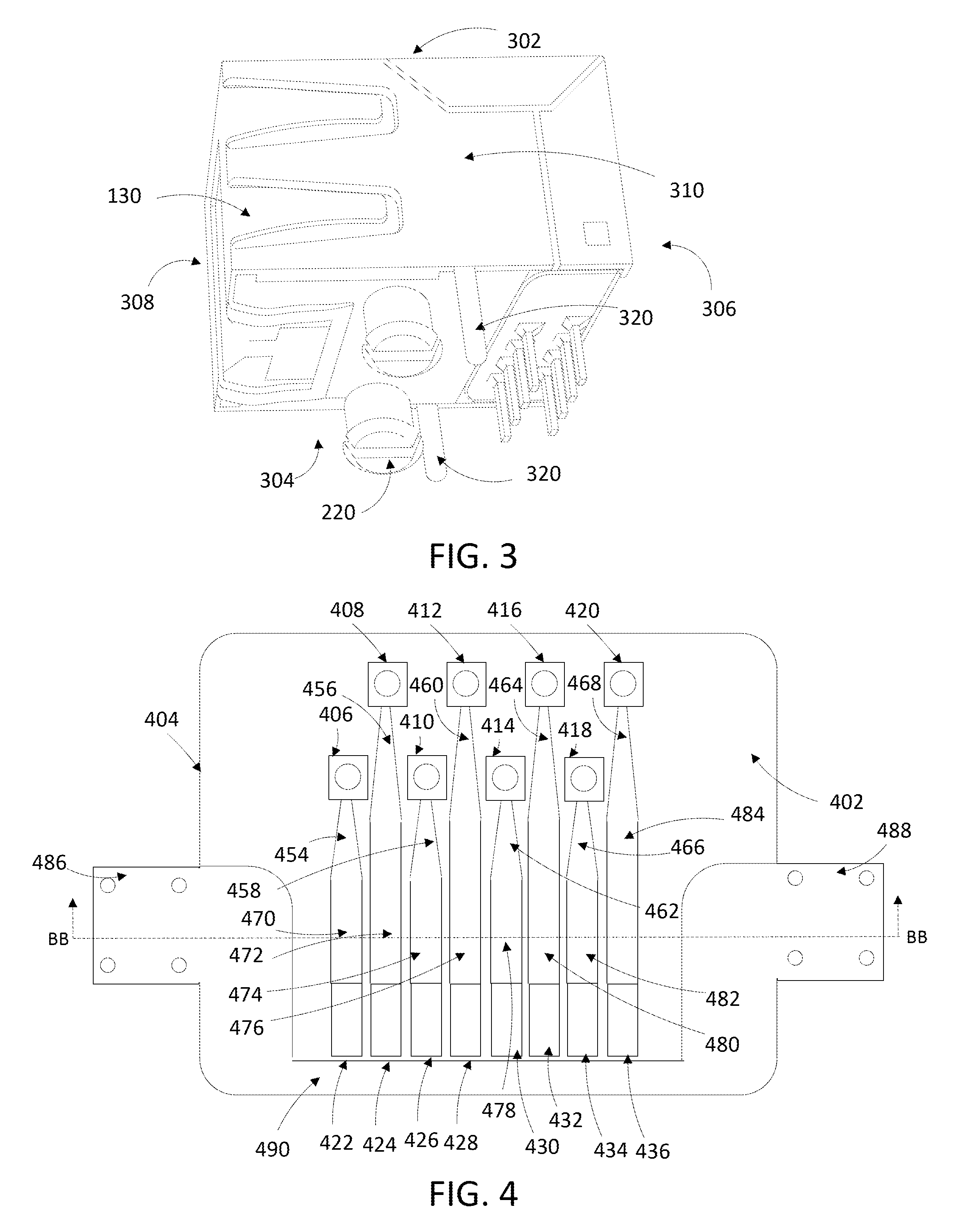
[0035]FIG. 1 illustrates a high speed communications jack configured in accordance with one embodiment of the various aspects of the present disclosure that includes an RJ45 jack 110, a flexible printed circuit board (PCB) 120, and a jack shield 130. As described herein, in accordance with various aspects of this disclosure, the flexible PCB 120 provides a balanced, radio frequency tuned circuit that may be directly soldered onto each pin of the RJ45 jack 110, while the jack shield 130 provides shielding for the RJ45 jack 110 and the flexible PCB 120, as well as functioning as a chassis ground. In combination, the RJ45 jack 110, the flexible PCB 120, and the jack shield 130 may provide functionality similar to a tuned waveguide and a tube through which communication signals may be transmitted, where an energy portion of the communication signal travels outside the tube through jack shield 130; and an information portion of the communication signal travels within the tube along the n...


PUM

PropertyMeasurementUnit
Dielectric polarization enthalpyaaaaaaaaaa
Electrical conductoraaaaaaaaaa
Widthaaaaaaaaaa

Abstract

A high speed communication jack including a housing including a port for accepting a plug, the port including a plurality of pins each connected to a corresponding signal line in the plug and a shielding case surrounding the housing. A flexible circuit board between the shielding case and the housing having a substrate, a plurality of vias extending through the substrate with each via being configured to accommodate a pin on the housing, a plurality of traces on a first side of the substrate, with each trace extending from a corresponding one of the plurality of vias, and a shielding plane on a second side of the substrate opposite the first side of the substrate.

Description

CROSS-REFERENCE TO RELATED APPLICATIONS[0001]The present disclosure claims priority to U.S. Provisional Patent Application No. 61 / 598,288, entitled “HIGH SPEED JACK” filed on Feb. 13, 2012, which is incorporated by reference herein in its entirety.FIELD OF THE DISCLOSURE[0002]The present disclosure relates to a network connection jack used to connect a network cable to a device.BACKGROUND OF THE DISCLOSURE[0003]As electrical communication devices and their associated applications become more sophisticated and powerful, their ability to gather and share information with other devices also becomes more important. The proliferation of these intelligent, inter networked devices has resulted in a need for increasing data throughput capacity on the networks to which they are connected to provide the improved data rates necessary to satisfy this demand. As a result, existing communication protocol standards are constantly improved or new ones created. Nearly all of these standards require ...

Claims


Application Information

Patent Timeline
IPC IPC(8): H01R13/646H01R43/20
CPCH01R13/646H01R43/205Y10T29/49218H01R24/64H01R13/6474H01R13/7195H01R13/6466Y10T29/49165H01R13/6581H01R13/6625H01R13/6658H01R2107/00H05K1/0218H05K1/0228H05K1/09H05K1/115H05K1/162
Inventor ROBINSON, BRETT D.
Owner SENTINEL CONNECTOR SYST
Features
  • Generate Ideas
  • Intellectual Property
  • Life Sciences
  • Materials
  • Tech Scout
  • Unparalleled Data Quality
  • Higher Quality Content
  • 60% Fewer Hallucinations
Learn More