Heat exchange unit for self-cooling containers

Inactive Publication Date: 2013-08-22
JOSEPH CO INT INC
View PDF12 Cites 4 Cited by
  • Summary
  • Abstract
  • Description
  • Claims
  • Application Information

AI Technical Summary

Benefits of technology

[0012]An improved HEU for use within a self-cooling container, the HEU comprising a metal shell having a closed bottom and an open top, a compacted adsorbent material disposed internally of the shell, a metal t

Problems solved by technology

Self-cooling devices utilized in the prior art exemplified by the above-identified patents are generally unsatisfactory.
Some of the difficulties which have been encountered are that the devices generally rely on toxic or environmentally unfriendly chemicals, require very bulky pneumatic circuits and cannot economically be used in small containers such as beverage cans or food cans, are rather complex, and thus are expensive to manufacture and maintain and are ineffective.
In addition, it has been found that if the pressure within the heat exchange unit increases to a predet

Method used


Image

  • Heat exchange unit for self-cooling containers
  • Heat exchange unit for self-cooling containers
  • Heat exchange unit for self-cooling containers

Examples


Example

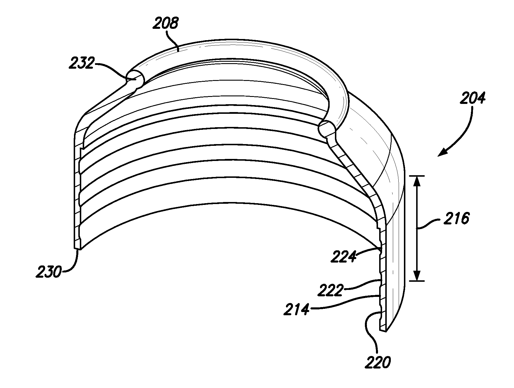
[0018]Referring now more particularly to FIG. 4, there is illustrated a HEU (200) which has a metal shell (202) and a metal top section (204) which is secured to the top of the shell (202) as will be described in more detail below.

[0019]The upper portion of the top section (204) of the HEU terminates in an opening (206) defined by a solid curl (208). The solid curl (208) receives a valve mechanism of the type generally above described in the prior art which is carried by a typical mounting member having a pedestal within which there is sealingly secured the appropriate dispensing valve. The valve includes the typical stem extending through the central opening in the pedestal and on a safety device that will open under excess pressure. The mounting member is inserted into the opening (206) at the top section and the outer periphery thereof and is affixed to the curl (208) by way of a crimping operation as is well known to those skilled in the art. The crimping operation not only secu...


PUM


Abstract

A heat exchange unit (HEU) for positioning internally of a container for housing a food or beverage, the HEU including a metal shell having an outer surface, and a metal top section having a skirt, which fits over the outer surface of the metal shell and is permanently secured to said metal shell by an adhesive material, compressed carbon particles are disposed within said metal shell and carbon dioxide gas is adsorbed by said carbon particles and upon activation of a valve secured to said top section desorbs to cool the food or beverage.

Description

RELATED APPLICATION[0001]This application is based on U.S. Provisional Application No. 61 / 327,516 filed Apr. 23, 2010, filed as PCT / US2011 / 032715 with international filing date of 15 Apr. 2011 for Heat Exchange Unit for Self-Cooling Containers and claims the benefit of the filing date thereof.BACKGROUND OF THE INVENTION[0002]1. Field of the Invention[0003]This invention relates generally to containers housing a pressurized medium such as self-chilling or self-heating food and beverage containers and more particularly to an improved heat exchange unit which is housed within a self-cooling container for cooling a product such as a food or beverage wherein the heat exchange unit is secured within the container and houses the pressurized medium.[0004]2. Description of Prior Art[0005]It has long been desirable to provide a simple, effective and safe device which may be housed within a container such as a food or beverage container for the purpose of cooling or heating a product such as f...

Claims


Application Information

Patent Timeline
IPC IPC(8): F25D7/00
CPCF25D2331/805F25D7/00
Inventor CULL, DAVIDSILLINCE, MARK
Owner JOSEPH CO INT INC
Why Eureka
Try Eureka